The F5 BIG-IP HA feature provides redundancy and load balancing capabilities for your BIG-IP devices.
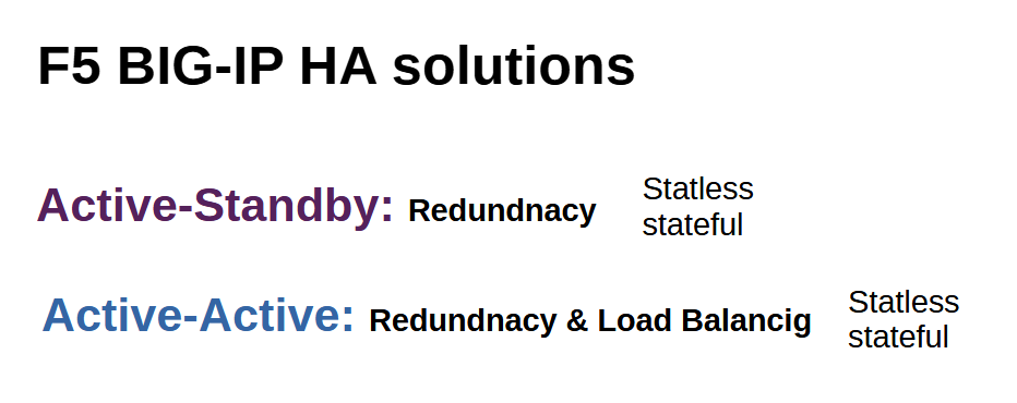
In this section we will implement BIG-IP HA Active-Standby which bring redundancy to your network. In the next sections we will also discuss BIG-IP HA Active-Active configuration which bring both redundancy and load balancing.
Providing a solution for redundancy or fail-over is important. Therefore, if a critical network component fails, there is minimal disruption to network users and services. This is also true for F5 BIG-IP devices.
With redundancy, if one BIG-IP device fails, the other BIG-IP device takes over responsibility for processing traffic. This is implemented using BIG-IP Active-Standby HA.
With the load balancing feature, both BIG-IP devices process traffic for different applications to avoid overloading a particular BIG-IP device. It also provides redundancy if a BIG-IP device fails. This is implemented using BIG-IP Active-Active HA.
BIG-IP HA solution has stateless and stateful options.
With stateless, existing connection sessions are not copied to the redundant BIG-IP. Therefore, during fail-over, existing connections are disrupted, but new connections can be regenerated.
With stateful, existing connection sessions are copied also to the redundant BIG-IP device, so fail-over has no effect on existing connections.
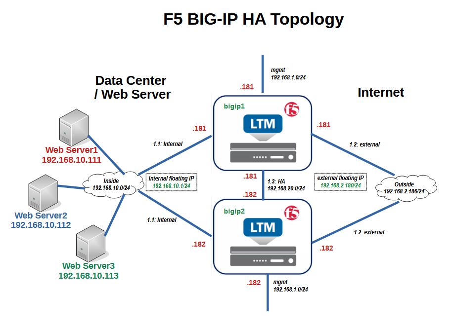
This is the topology of F5 BIG-IP HA solution that we will implement in this section.
There are two BIG-IP devices with the name of “bigip1” and “bigip2”, both connected to the internal networks with the subnet 192.168.10.0/24 where the pool member servers are connected. Both are connected to the external network with subnet 192.168.2.0/24 for internet connectivity. They are also connected to the management network with subnet 192.168.1.0/24 for management access and finally to the HA networks with subnet 192.168.20.0/24 for configuration and connection synchronization between BIG-IP devices.
In the previous sections, we did not use the HA interface, but it is required for implementing BIG-IP HA solutions. Therefore, it is configured in this section. HA interface will be used to synchronize configuration between BIG-IP devices. Optionally, it can be used to replicate live connections between BIG-IP devices in a stateful HA solution.
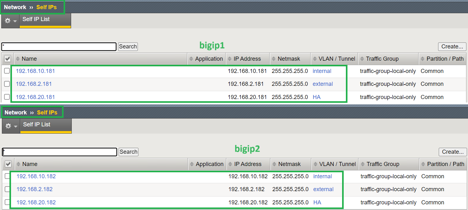
In all networks, the IP address of BIG-IP device1 is .181 and the IP address of BIG-IP device2 is .182.
For internal and external interfaces, which are also called data interfaces, we need to configure floating IP addresses.
Floating IP addresses are the same in both BIG-IP devices, but are only active in the active BIG-IP device. Servers and devices that point to BIG-IP as a gateway use the floating IP address.
If active BIG-IP devices fail, the floating IP address is moved to the next active BIG-IP. Therefore, servers and devices that point to BIG-IP as a gateway are not disrupted.
To begin the F5 BIG-IP HA configuration, we start with the VLANs and IP configuration to ensure it matches the topology.
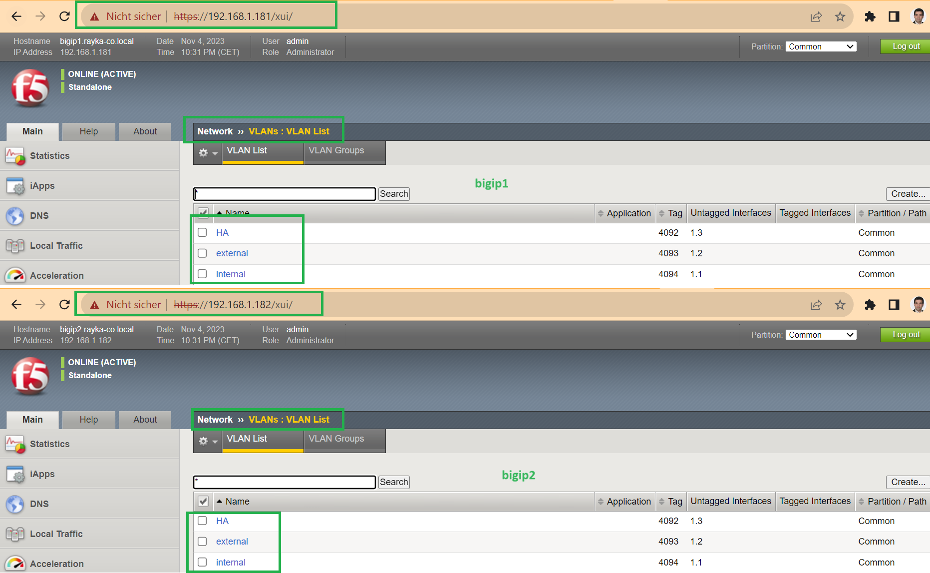
I have already configured internal and external VLANs. Let’s also add the new HA VLAN which is required in HA configuration. It must be added in both bigip1 and bigip2 devices.
Interface 1.1 is in internal VLAN, interface 1.2 is in external VLAN and now interface 1.3 is used for HA VLAN.
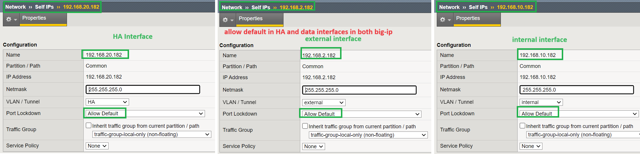
Then we configure the IP address of the new HA interface according to the topology.
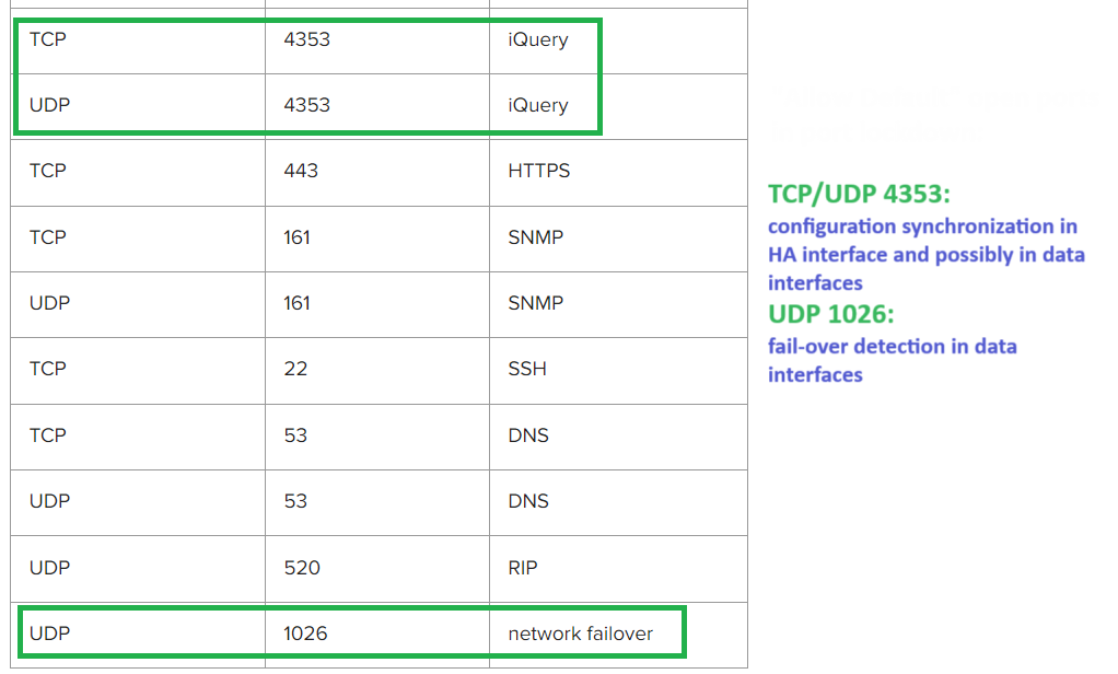
For “port lockdown” in HA interface, it is important to make sure that TCP/UDP ports 4353 is open which is used for configuration synchronization.
We can use custom ports to add the port or we choose “Allow Default” just for the simplicity which include TCP/UDP port 4353.
For internal and external data interfaces, also ensure that at least port UDP 1026 is open, which is used for fail-over detection.
We can use custom ports to add the port or we choose “Allow Default” just for the simplicity which include UDP port 1026.
This is the list of open ports when you choose “Allow Default” in port lockdown option. As you can see both TCP/UDP 4353 and UDP 1026 are open in default lockdown ports.
Then we are ready to configure HA parameters.
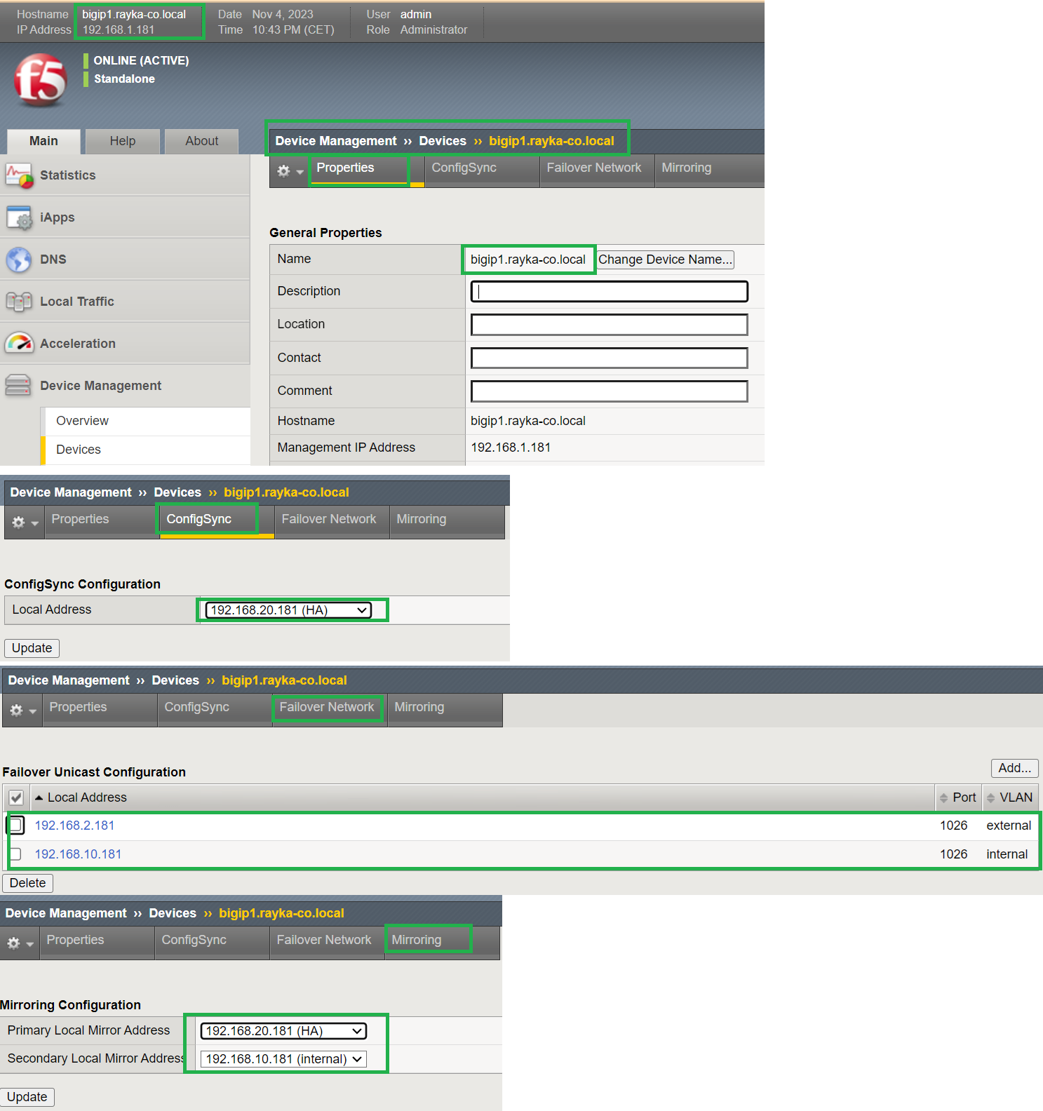
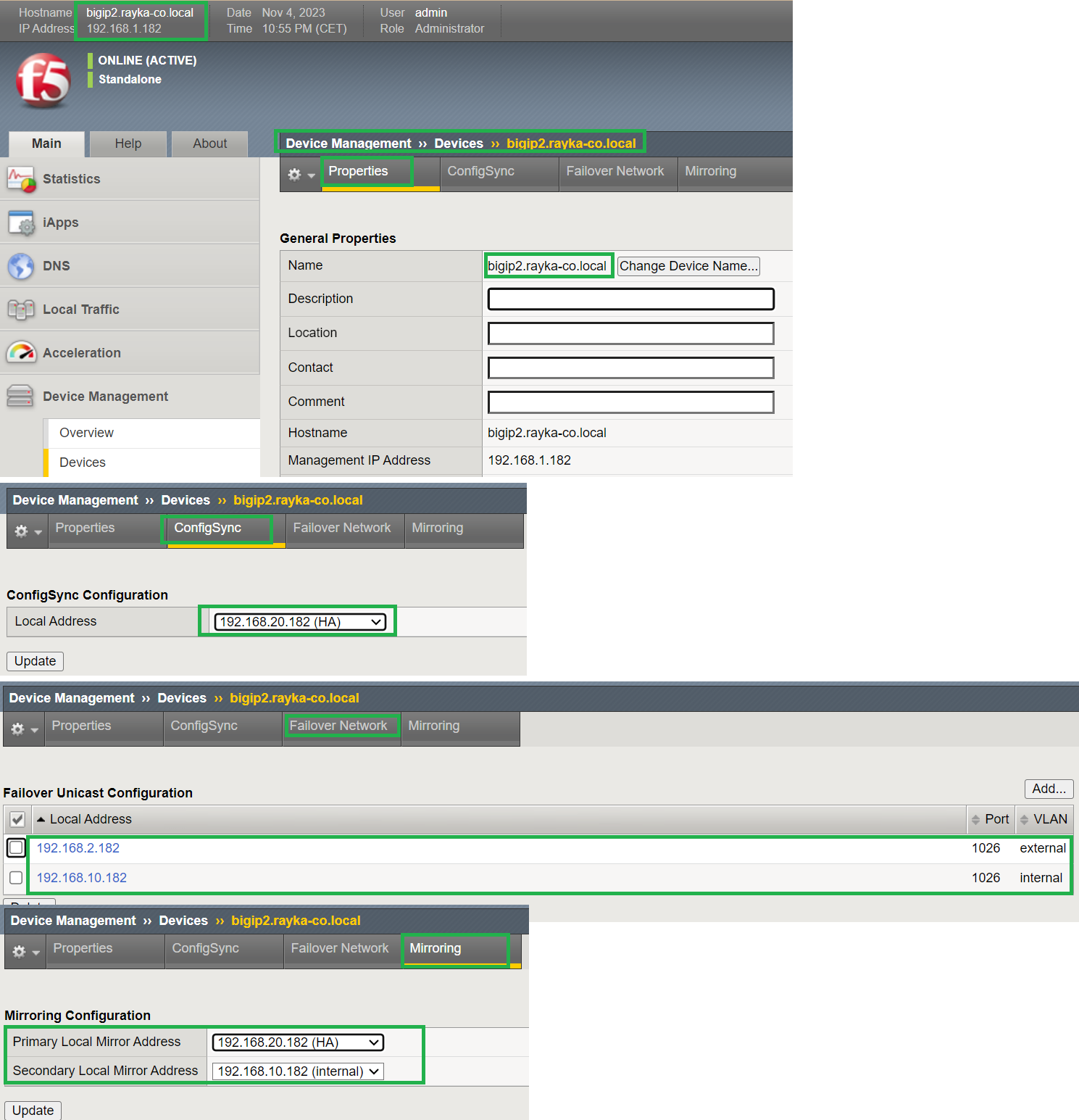
For both BIG-IP devices, under “Device Management”, “Devices” section, of the Properties tab, ensure that the device name and management IP address are already configured or change the device name according to your design.
Under the “ConfigSync” tab, specify the interface through which configuration synchronization will occur. We choose always HA interface to be used for configuration synchronization.
Under the “Failover Network” tab, we select the list of interfaces for failover detection. Typically we add all data and management interfaces except HA interface for failover detection.
Under the “Mirroring” tab, we specify the interface in which the live connection table will be replicated between BIG-IP devices.
We usually configure a dedicated interface for connection mirroring because large amounts of data usually need to be transferred. The HA interface is the second option that can be used for mirroring.
Here we choose HA and an internal interface for connection mirroring.
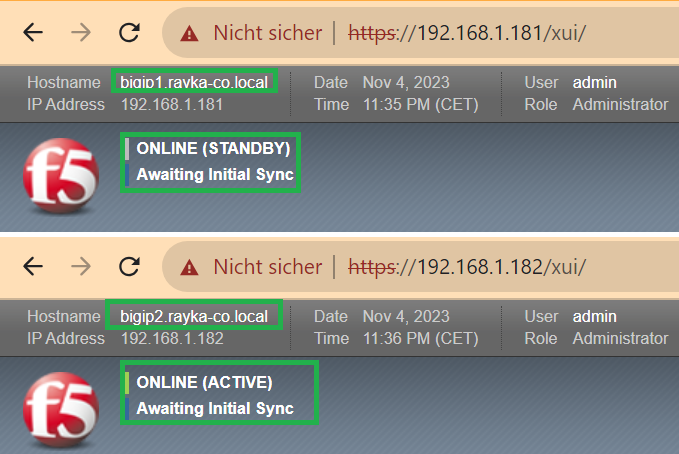
Note that BIG-IP devices are still in a standalone state.
In the next step, we configure “device trust” between BIG-IP devices.
This is enough to be done in one of the BIG-IP devices. In the other device will be added automatically.
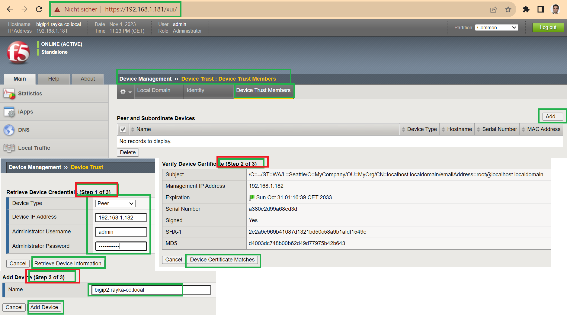
Under “Device Management“, “Device Trust“, and “Device Trust Members“, we add the management IP address, and the username, and password to retrieve device information. We then confirm the certificate and finally add the peer device to be trusted.
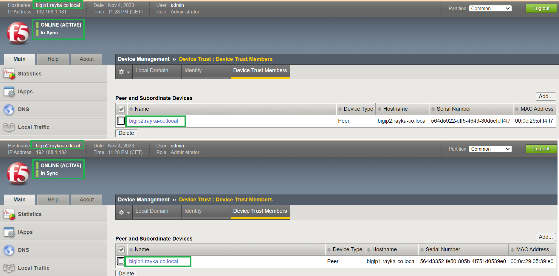
It will be then added in both devices.
Also notice that both devices are now in the active state.
In the next step we configure the device group.
What is F5 BIG-IP device group?
Device groups contain devices that can synchronize their configuration and also fail over to another device if one device fails. Up to eight devices can be added to a device group.
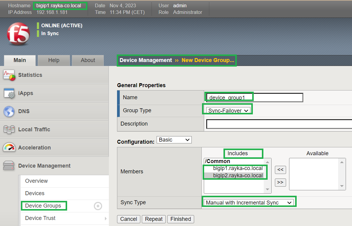
Under “Device Management”, “Device Groups” we create a new device group and include both BIG-IP devices in the device group.
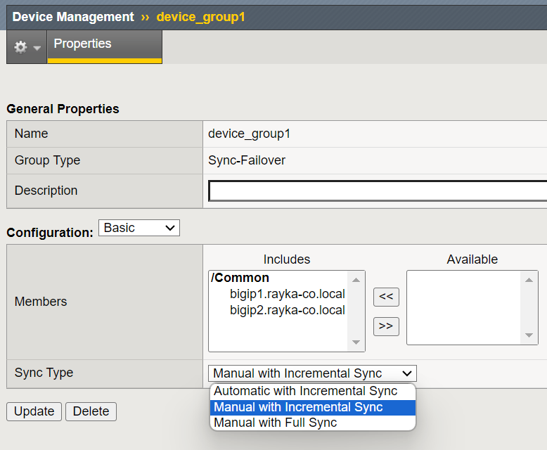
The “Sync Type” option offers the option to synchronize the configuration manually or automatically. For HA configuration, it is recommended to use manual synchronization. However, you can then change it later to automatic synchronization.
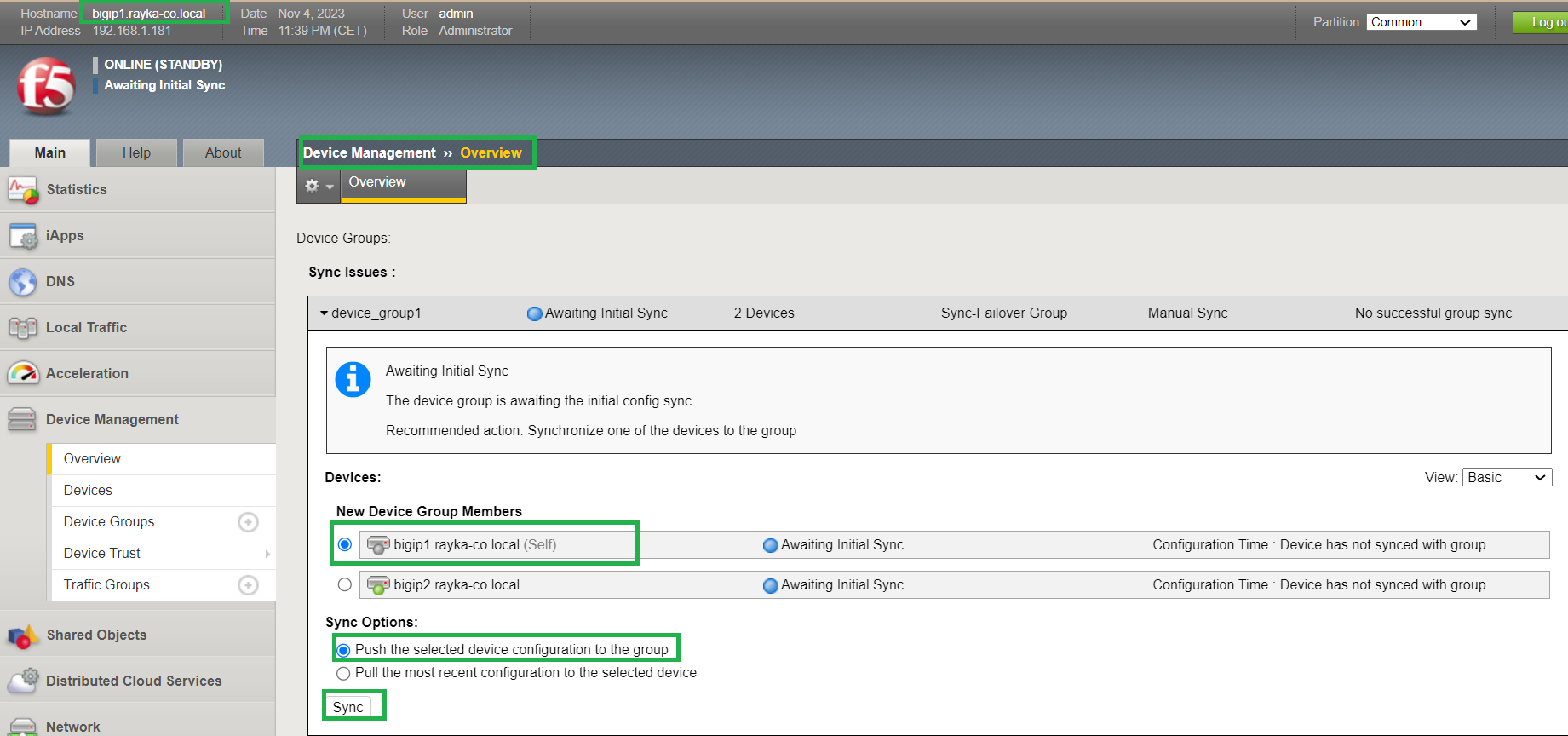
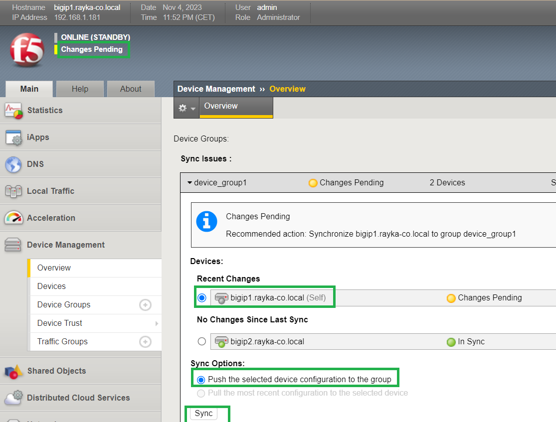
Now we synchronize the configuration from bigip1 to all other devices in device group.
You can click over „Awaiting Initial Sync“ or under „Device Management“, „Overview“, you can synchronize the configuration manually.
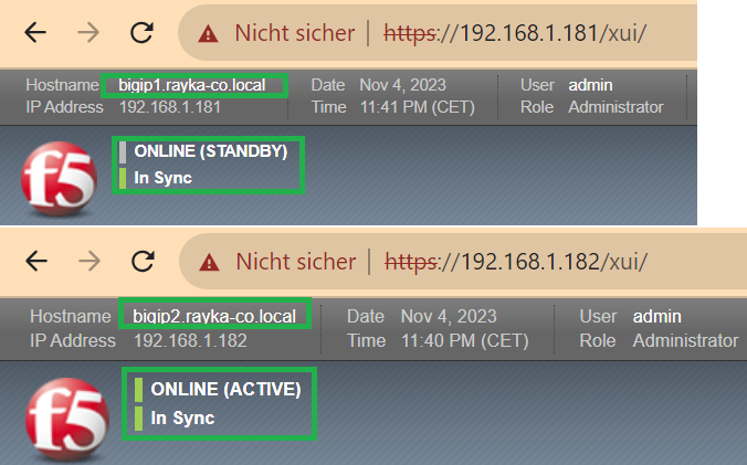
After configuration synchronization, BIG-IP devices are in “Active-Standby” state and “In Sync” state.
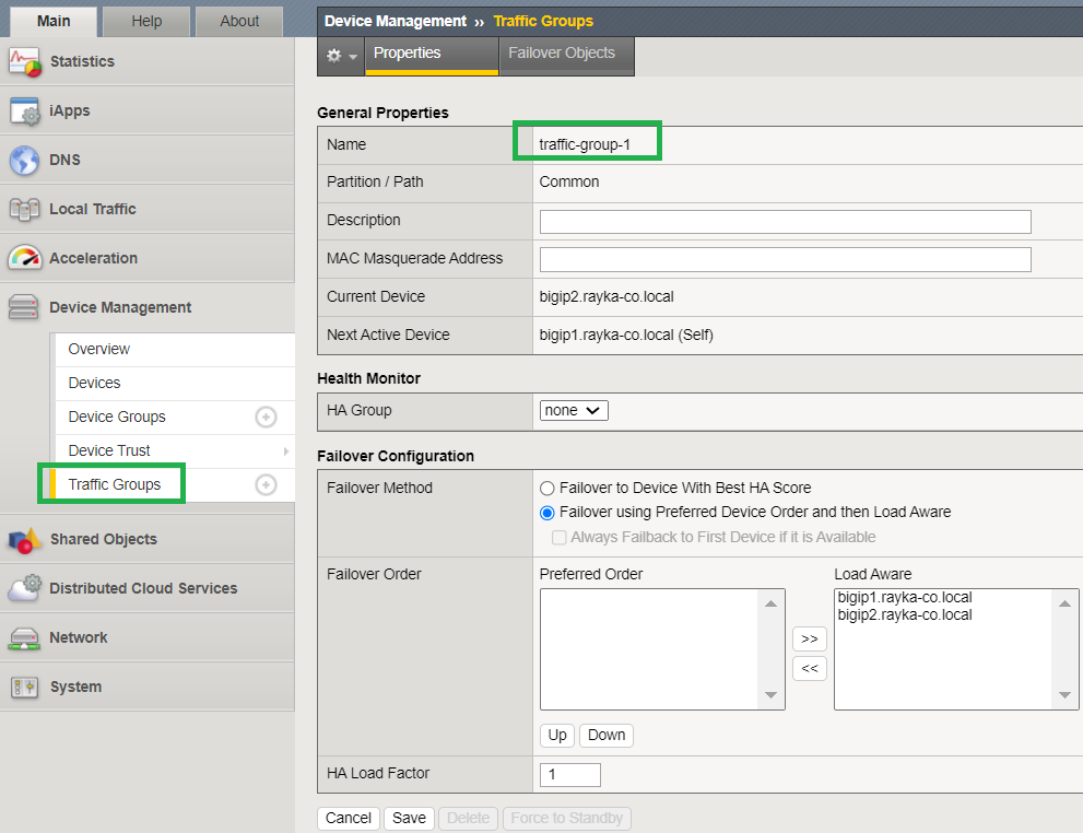
In the next step, we will check the traffic group that is automatically created when you create a device group.
What is F5 BIG-IP traffic group? And what is the relationship with device group?
Traffic group allows you to route a collection of traffic to a specific BIG-IP device in a device group.
With multiple traffic groups, we can route traffic from different applications to different BIG-IP devices in the same device group. This is exactly what we will implement in the F5 BIG-IP Active-Active HA configuration.
As we’ll see shortly, for each traffic group a collection of floating IP addresses is assigned.
For each traffic group, you can configure which device is preferred manually or based on the A score. you can assign an “HA group” to a traffic group. You can also configure „HA Load Factor“. All these concepts will be explained in the next sections.
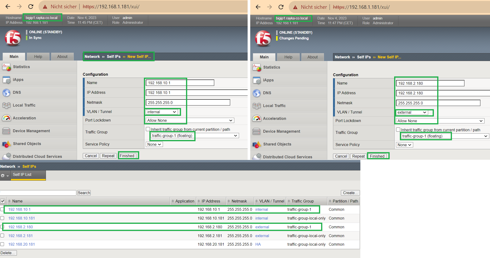
In the next step, we configure internal and external floating self-IP that will be shared by BIG-IP devices and assigned to the traffic group.
These configurations are performed in one of the BIG-IP devices in the device group. The new changes are then synchronized with other BIG-IP devices in the device group.
Based on the design, IP address 192.168.10.1 is configured for internal self-IP and IP address 192.168.2.180 is configured as external self-IP.
No ports need to be open for Self-IP in the HA configuration. Therefore, we select the “Allow None” option in the “Port Lockdown” field.
We will also assign the floating IP to “Traffic Group-1”, the only traffic group in this scenario.
Now we will sync the new changes to other BIG-IP devices in the “Device Management”, “Overview” section.
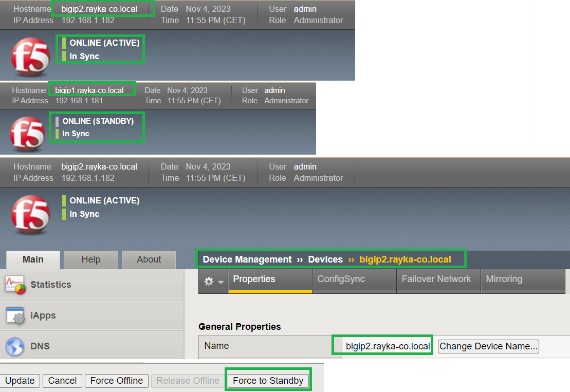
Now devices are in “active-standby” and „In Sync“ state.
To manually change the active HA device, connect to the device that is now active in the HA configuration. In the section „Device Management“, „Devices“, click on the active device.
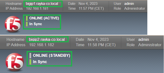
At the bottom of this page there is a “Force to Standby” button. Clicking this button is expected to move the active device role to the next device in the device group.
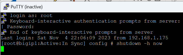
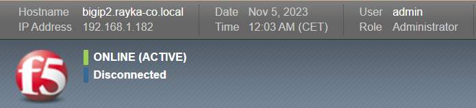
In the final step, we shut down the active HA device to ensure that the active device is automatically moved to the next device.
To some extent, we have configured HA in F5 BIG-IP devices. But that is not all.
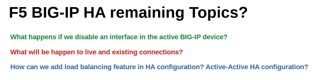
What happens if we disable an interface in the active BIG-IP device? Active device is moved to the other device?
What will be happen to live and existing connections? They will be disrupted?
How can we add load balancing feature in HA configuration? How is Active-Active HA configured in F5 BIG-IP devices?
All of these questions will be answered in the coming sections.