Cisco SD-WAN service chaining allows us to force traffic through some central services like firewall and IPS before it is forwarded to the destination.
However, service chaining is not supported in CSR1000v but I will try to show the concept and configuration except for final result.
Cisco SD-WAN Service Chaining overview
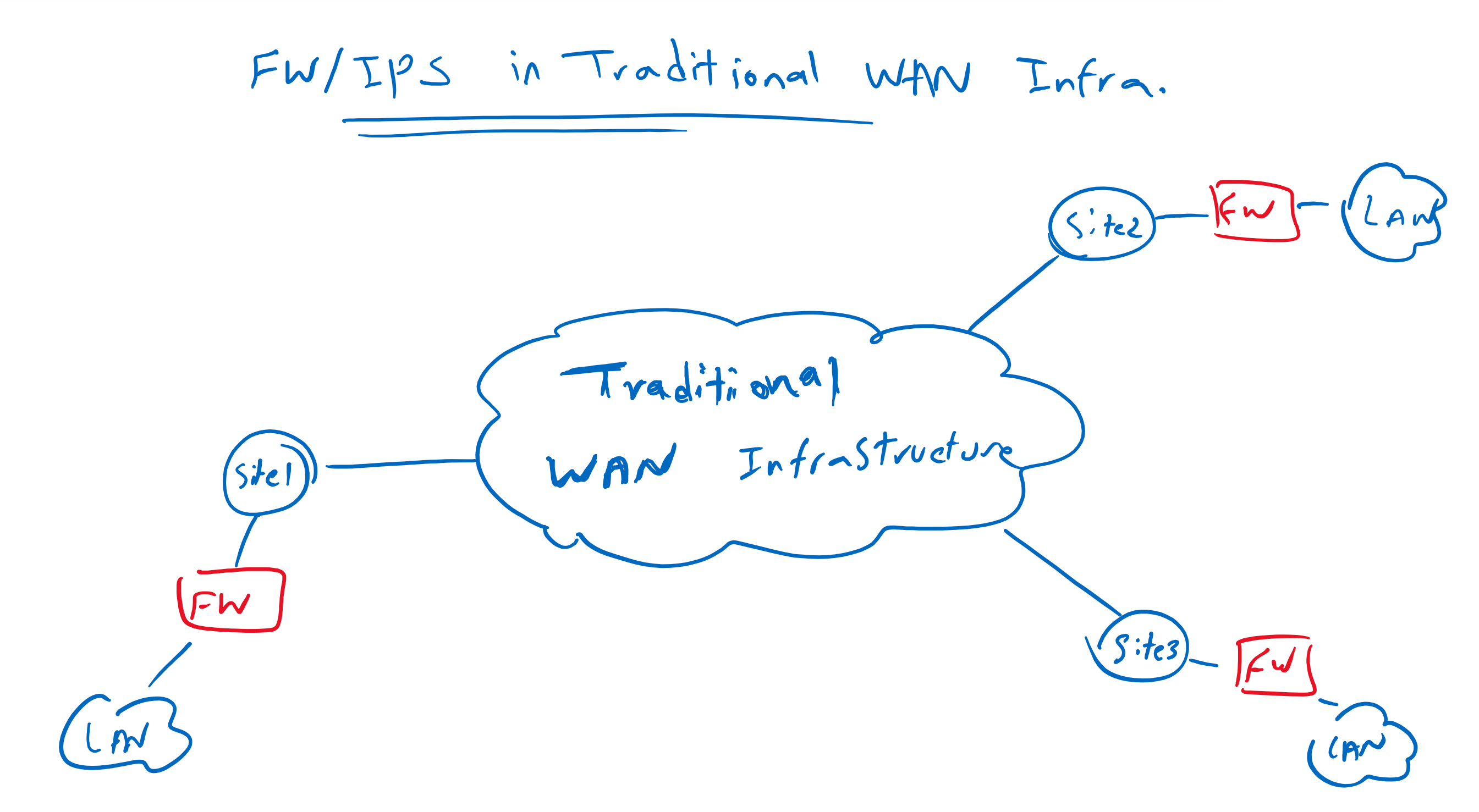
Firewall Service in Traditional WAN Infrastructure
In traditional WAN infrastructure, we usually configure firewall and IPS in all branches in order to force forwarding of data traffic through security services. Otherwise it is not impossible but very difficult to route traffic to a central firewall and IPS services.
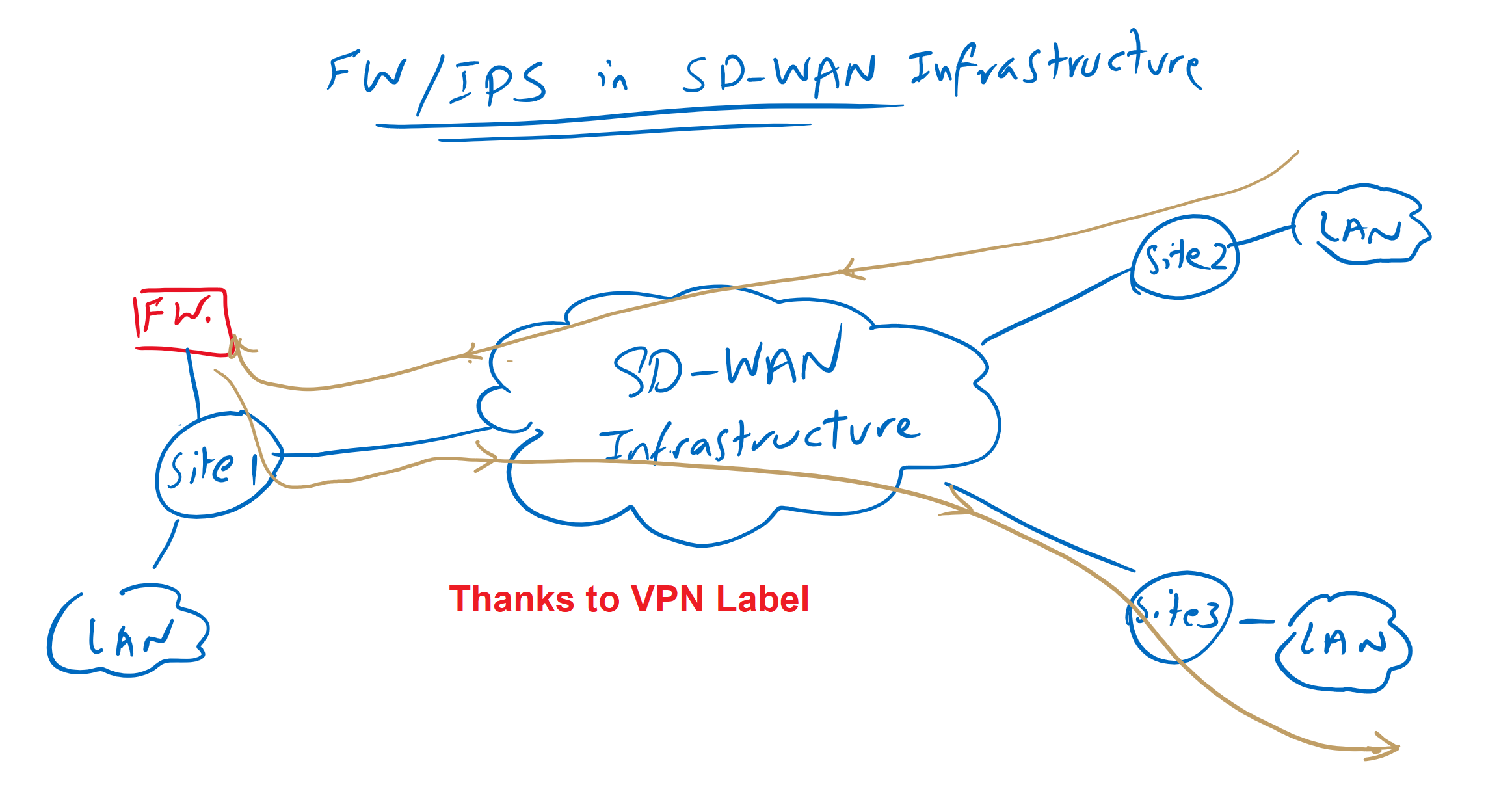
Service Chaining in cisco SD-WAN Infrastructure
In cisco SD-WAN infrastructure, however, it is easily possible to force data traffic through a central firewall/IPS without having to configure a complex routing policy. Thanks to VPN label that made this possible.
Direct Traffic through central firewall VPN Service
To see how forwarding traffic through central services are possible, let’s first review our topology.
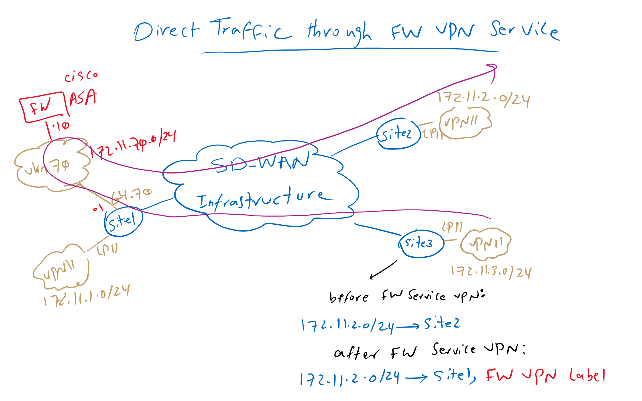
I’m assuming you are familiar with the concept of Cisco SD-WAN VPN label, discussed in the last two videos with the name of “28. Cisco SD-WAN VPN label “. It is also assumed that you studied the previous video where I added a Cisco ASA firewall in Site1. ASA Firewall is added through sub-interface in VLAN 70 in VPN 11.
Just to review, one ASA firewall is centrally located in site1 with just one link. It is connected with IP address 172.11.70.10 with tag VLAN 70. It’s default route points to site1 WAN edge router with ip address 172.11.70.1 in the same VLAN and in VPN 11.
Who are familiar with firewall design, know that connecting firewall with just one link is a not a normal design to forward and inspect traffic. But in cisco SD-WAN infrastructure, just one link can be enough when link bandwidth is not a limitation.
However, ASA firewall is connected to VPN 11, but it doesn’t mean that it is limited to inspecting VPN 11 traffic. Traffic related to any service VPN including VPN 10, can be forwarded through this firewall, provided that the IP address of the ASA firewall is routable to other service VPNs. In the previous sections we have seen how routing between VRF or VRF route leaking in Cisco SD-WAN infrastructure works.
Another point in this topology is that Site2 and Site3 can connect directly to each other before implementing firewall service VPN. In other words, the next hop address for the subnet behind Site2 172.11.2.0/24 points to the Site2 edge router itself.
But after firewall VPN service is implemented, vSmart controller change the next-hop address for the same subnet 172.11.2.0/24 to points to site1 edge router which host firewall service VPN.
As you know, in addition to prefixes, VPN labels are also advertised using OMP routing protocol between sites. Therefore, all sites know exactly the label which is assigned to the firewall VPN service in Site1 edge router.
The firewall VPN label is critical to completing the routing process through the firewall VPN service.
Cisco SD-WAN Service Chaining Traffic Flow
Now the question is how is exactly traffic flow between site2 and site3?
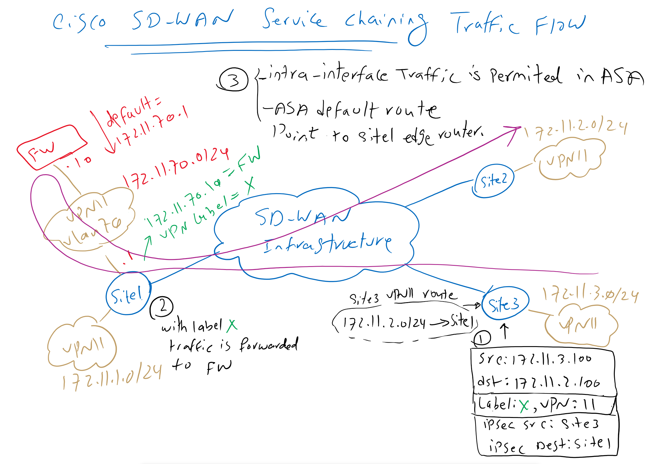
As an example, suppose a traffic is generated with source IP 172.11.3.100 and destination IP 172.11.2.100. site3 edge router receive traffic through a link in VPN 11. It looks up VRF 11 routing table and know that it must be forwarded to site1 and VPN label X.
The data traffic is encapsulated in an IPsec tunnel between Site3 and Site1. Site1 receives the traffic with VPN label X and with VPN label X it knows that it must be forwarded to the firewall service VPN.
The feature “same-security-traffic permit intra-interface” is already enabled in ASA firewall which allows traffic to be received and forwarded in the same interface.
The default route in Cisco ASA points to Site1’s edge router. After inspecting the traffic, it returns the traffic back to Site1’s edge router.
Site1 edge router receive the traffic in VPN 11. Lookups VPN11 routing tables and forward it normally through IPsec tunnel to site2.
The same process will be repeated for reverse traffic which is not displayed here.
Cisco SD-WAN Service Chaining Configuration
Before we configure firewall service VPN, let’s check Site3’s routing table to make sure, there is a direct connection between Site2 and Site3.
cEdge3#show ip route vrf 11

Routing Table: 11
....

Gateway of last resort is 0.0.0.0 to network 0.0.0.0

n*Nd  0.0.0.0/0 [6/0], 5d04h, Null0
      172.11.0.0/16 is variably subnetted, 7 subnets, 2 masks
m        172.11.1.0/24 [251/0] via 1.1.1.101, 00:00:24
m        172.11.2.0/24 [251/0] via 1.1.1.102, 00:00:24
C        172.11.3.0/24 is directly connected, Loopback11
L        172.11.3.1/32 is directly connected, Loopback11
m        172.11.4.0/24 [251/0] via 1.1.1.104, 00:00:24
m        172.11.70.0/24 [251/0] via 1.1.1.101, 00:00:24
m        172.11.80.0/24 [251/0] via 1.1.1.101, 00:00:24
Again, it is assumed that Cisco ASA firewall was already added in the Cisco SD-WAN infrastructure as I demonstrated in the previous video.
Since we will only add the firewall service VPN in Site1 and in Service VPN 11, we copy the current VPN11 feature template into a new VPN11 feature template just to be applied to the edge router of Site1.
CONFIGURATION -> TEMPLATES -> Feature -> CSR1000v_VPN11 -> Copy to CSR1000v_VPN11_FWThen we add firewall service VPN in newly created feature template.
CONFIGURATION -> TEMPLATES -> Feature -> CSR1000v_VPN11_FW -> Edit
 Section: Service -> New Service
  Service Type: FW
  IPv4 address: 172.11.70.10
Now this new feature template must be used as a replace in cedge1 router.
Before removing and replacing VPN11 service VPN in cEdge1 router, we review the current configuration details so exact configuration will be copied in replacing service VPN.
CONFIGURATION -> TEMPLATES -> Device -> CSR1000v_Device_Template_cEdge1 -> Edit
 Section: Service VPN
# just check the configuration before removing and replacing it with new VPN11 Service VPN
  Template Name: CSR1000v_VPN11 -> Edit
   Cisco VPN Interface Ethernet: CSR1000v_VPN11_Loopback11
   Cisco VPN Interface Ethernet: CSR1000v_VPN11_GigabitEthernet4_VLAN70
   Cisco VPN Interface Ethernet: CSR1000v_VPN11_GigabitEthernet4_VLAN80

# now remove VPN11 Service VPN and replace it with new one
  Select
   Template Name: CSR1000v_VPN11 -> Remove VPN

  Add VPN
    CSR1000v_VPN11_FW
     Cisco VPN Interface Ethernet: CSR1000v_VPN11_Loopback11
     Cisco VPN Interface Ethernet: CSR1000v_VPN11_GigabitEthernet4_VLAN70
     Cisco VPN Interface Ethernet: CSR1000v_VPN11_GigabitEthernet4_VLAN80
When we preview the configuration , we see that the only configuration changes is to configure firewall IP address in VPN 11.
sdwan
 service firewall vrf 11
  ipv4 address 172.11.70.10
After adding the VPN firewall service, we expect that a VPN label will be assigned to this new service. But as I said at the beginning of this text, it is not supported in CSR1000v and we cannot see it.
cEdge1#show sdwan omp services
C   -> chosen
I   -> installed
Red -> redistributed
Rej -> rejected
L   -> looped
R   -> resolved
S   -> stale
Ext -> extranet
Stg -> staged
Inv -> invalid
ADDRESS                                               PATH
FAMILY   VPN    SERVICE  ORIGINATOR  FROM PEER        ID     LABEL    STATUS
--------------------------------------------------------------------------------
ipv4     10     VPN      1.1.1.101   0.0.0.0          69     1001     C,Red,R
         11     VPN      1.1.1.101   0.0.0.0          69     1002     C,Red,R
         65528  VPN      1.1.1.101   0.0.0.0          69     1003     C,Red,R
ipv6     10     VPN      1.1.1.101   0.0.0.0          69     1001     C,Red,R
         11     VPN      1.1.1.101   0.0.0.0          69     1002     C,Red,R
Now we can create a custom topology to forward traffic between site2 and site3 through firewall VPN service.
CONFIGURATION -> POLICIES -> Custom Options -> Topology -> Add Topology -> Custom Control
 Name: REDIRECT_TO_FW
 Description: REDIRECT_TO_FW
  Sequence Type: Route
   Rule 1:
    Match:
     VPN: VPN List = VPN11
    Actions:
     Accept &
     Service:
      Service Type: Firewall
      Service VPN: 11
   Default Action: Accept
And then the new topology must be applied to vSmart controller through centralized policy.
CONFIGURATION -> POLICIES -> Centralized Poliy -> Add Policy -> Configure Topology and VPN Membership -> Add Topology -> Import Existing Topology -> Custome Control -> Policy: REDIRECT_TO_FW -> Next -> Next -> Apply Policies to Sites and VPNs
 Policy Name: vSmart_Controller
 Policy Description: vSmart_Controller
  Topology
   REDIRECT_TO_FW
    New Site List
     Outbound Site List: SITE2, SiSITE3
Now we can preview the configuration which is applied in vSamrt controller.
viptela-policy:policy
 control-policy REDIRECT_TO_FW
    sequence 1
     match route
      vpn-list VPN11
      prefix-list _AnyIpv4PrefixList
     !
     action accept
      set
       service  FW vpn 11
      !
     !
    !
  default-action accept
 !
 lists
  site-list SITE2
   site-id 102
  !
  site-list SITE3
   site-id 103
  !
  vpn-list VPN11
   vpn 11
  !
  prefix-list _AnyIpv4PrefixList
   ip-prefix 0.0.0.0/0 le 32
  !
 !
!
apply-policy
 site-list SITE3
  control-policy REDIRECT_TO_FW out
 !
 site-list SITE2
  control-policy REDIRECT_TO_FW out
 !
!
Then the policy must be activated.
CONFIGURATION -> POLICIES -> Centralized Poliy -> Activate After applying the policy, we expect that next-hop address in site2 and site3 will be changed to site1 which firewall service is located. Bute here we can not see what we expect since it is not supported in CSR1000v.
cEdge3#show ip route vrf 11

Routing Table: 11
...

Gateway of last resort is 0.0.0.0 to network 0.0.0.0

n*Nd  0.0.0.0/0 [6/0], 4d16h, Null0
      172.11.0.0/16 is variably subnetted, 2 subnets, 2 masks
C        172.11.3.0/24 is directly connected, Loopback11
L        172.11.3.1/32 is directly connected, Loopback11


cEdge2#show ip route vrf 11

Routing Table: 11
...
Gateway of last resort is 0.0.0.0 to network 0.0.0.0

n*Nd  0.0.0.0/0 [6/0], 4d16h, Null0
      172.11.0.0/16 is variably subnetted, 2 subnets, 2 masks
C        172.11.2.0/24 is directly connected, Loopback11
L        172.11.2.1/32 is directly connected, Loopback11
This is the whole process of enabling service chaining in a Cisco SD-WAN infrastructure that is super easy to implement.