Cisco SD-WAN Route Leaking enables communication between different service VPNs. By default, no communication between different VRF or Service VPNs are allowed.
Cisco SD-WAN Service VPN Overview
When we install cisco sd-wan controllers or wan edge routers, by default there are two VRFs, VRF 0 for transports and vrf 512 for out of band management.
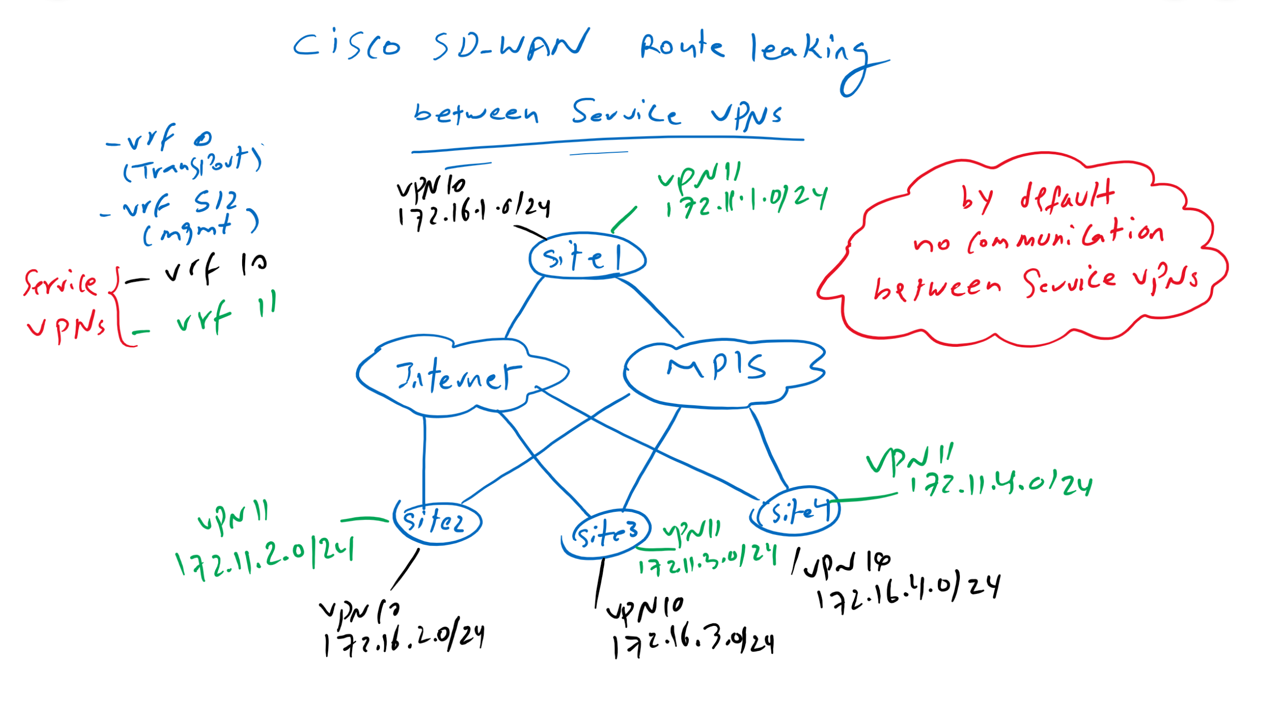
We are allowed to create many service VPN or VRFs behind wan edge routers to isolate different services. For example voice and data can be created in two different vrfs since there is no communication requirement between these two services.
In our topology we have already created vrf 10 Service VPN with IP addresses in the subnet 172.16.0.0/16. In this section we will create a new service VPN in vrf 11 with the IP range 172.11.0.0/16.
By default, no communication between services in different vrf is possible. However, sometimes it is necessary to enable communication between some services in different VRFs.
Cisco SD-WAN Route Leaking Example
In our example we will activate the communication between vrf 10 and site3 in vrf 11. So all sites in vrf 10 are allowed to communicate with IP addresses in site3 in vrf 11.

Cisco SD-WAN route leaking configuration procedure
This can be implemented when routes between sites are advertised through vSmart controller. vSmart Controller control which routes from source VRF to which sites in destination VRF can be advertised.
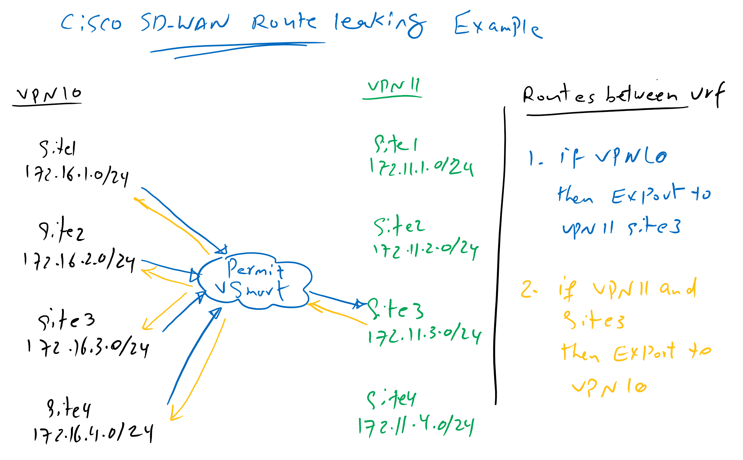
In our example, vSamrt controller advertise routes from vrf 10 to site3 in vrf 11 and vice versa, routes related to site3 in vrf 11 are advertised to all sites in vrf 10. Therefore, limited communication between two VRFs can be activated.
Cisco SD-WAN Route Leaking Configuration
Add Service VPN
Now we will start our configuration by creating a new service VPN in vrf 11 in edge routers.
First we create a new feature template for VPN 11.
CONFIGURATION -> TEMPLATES -> Feature -> Add Template -> CSR1000v -> Cisco VPN
 Template Name: CSR1000v_VPN11
 Description: CSR1000v_VPN11
  VPN: 11
  Name: VPN11
Then we create a new interface loopback 11 in the new service VPN.
CONFIGURATION -> TEMPLATES -> Feature -> Add Template -> CSR1000v -> Cisco VPN Interface Ethernet
 Template Name: CSR1000v_VPN11_Loopback11
 Description: CSR1000v_VPN11_Loopback11
  shutdown: No
  Interface Name: Loopback11
  IPv4 Address/ prefix-length: Device Specific (vpn11_loopback11_ipv4_address)
These new feature templates must be added to existing edge routers via device template. We have two device templates, one for the cedge1 router, “CSR1000v_Device_Template_cEdge1” and one for all other edge routers, “CSR1000v_Device_Template”. New feature templates must be added to both device templates. First we start with cedge1 router device template.
CONFIGURATION -> TEMPLATES -> Device -> CSR1000v_Device_Template_cEdge1 -> Edit
 Section: Service VPN
  Add VPN -> Add VPN11 Feature Template
   Cisco VPN Interface Ethernet: CSR1000v_VPN11_Loopback11
Then device specific new interface loopback 11 IP address must be added
Configure Device Specific Values:
 cEdge1: IPv4 Address/ prefix-length(vpn11_loopback11_ipv4_address)= 172.11.1.1/24
We have the opportunity to see the configuration changes. A new vrf, vrf 11 is created, then a new interface loopback 11 that is added in vrf 11.
vrf definition 11
 description VPN11
 rd          1:11
 address-family ipv4
  route-target export 65001:11
  route-target import 65001:11
  exit-address-family
 !
 address-family ipv6
  exit-address-family
!
!
interface Loopback11
 no shutdown
 arp timeout 1200
 vrf forwarding 11
 ip address 172.11.1.1 255.255.255.0
 no ip redirects
 ip mtu    1500
The same configuration must be added in CSR1000v_Device_Template, to apply the new service vpn in all other edge routers.
CONFIGURATION -> TEMPLATES -> Device -> CSR1000v_Device_Template -> Edit
 Section: Service VPN
  Add VPN -> Add VPN11 Feature Template
   Cisco VPN Interface Ethernet: CSR1000v_VPN11_Loopback11

Configure Device Specific Values:
 cEdge2: IPv4 Address/ prefix-length(vpn11_loopback11_ipv4_address)= 172.11.2.1/24
 cEdge3: IPv4 Address/ prefix-length(vpn11_loopback11_ipv4_address)= 172.11.3.1/24
 cEdge4: IPv4 Address/ prefix-length(vpn11_loopback11_ipv4_address)= 172.11.4.1/24
By default there is no communication between vrfs. This can be checked in routing table in vrf 10 and vrf 11.
cEdge1#show ip route vrf 10
Routing Table: 10
...
Gateway of last resort is 172.16.11.2 to network 0.0.0.0

S*    0.0.0.0/0 [1/0] via 172.16.11.2
      10.0.0.0/8 is variably subnetted, 3 subnets, 2 masks
O        10.1.0.1/32 [110/2] via 172.16.11.2, 5d15h, GigabitEthernet3
O E2     10.1.1.0/24 [110/20] via 172.16.11.2, 5d15h, GigabitEthernet3
S        10.1.2.0/24 [1/0] via 172.16.11.2
      172.16.0.0/16 is variably subnetted, 10 subnets, 2 masks
C        172.16.1.0/24 is directly connected, Loopback10
L        172.16.1.1/32 is directly connected, Loopback10
m        172.16.2.0/24 [251/0] via 1.1.1.102, 2d03h
m        172.16.3.0/24 [251/0] via 1.1.1.103, 2d03h
m        172.16.4.0/24 [251/0] via 1.1.1.104, 2d03h
C        172.16.11.0/24 is directly connected, GigabitEthernet3
L        172.16.11.1/32 is directly connected, GigabitEthernet3
m        172.16.12.0/24 [251/0] via 1.1.1.102, 2d03h
m        172.16.13.0/24 [251/0] via 1.1.1.103, 2d03h
m        172.16.14.0/24 [251/0] via 1.1.1.104, 2d03h
cEdge1#
!!!!
cEdge1#show ip route vrf 11
Routing Table: 11
...
Gateway of last resort is not set

      172.11.0.0/16 is variably subnetted, 5 subnets, 2 masks
C        172.11.1.0/24 is directly connected, Loopback11
L        172.11.1.1/32 is directly connected, Loopback11
m        172.11.2.0/24 [251/0] via 1.1.1.102, 00:03:04
m        172.11.3.0/24 [251/0] via 1.1.1.103, 00:03:00
m        172.11.4.0/24 [251/0] via 1.1.1.104, 00:03:03
cEdge1#
As you can see there is no route from vrf 10 in vrf 11 routing table and there is also no routes from vrf 11 in vrf 10 routing table.
Implementing Cisco SD-WAN Route Leaking between VRFs
Now we can start to redistribute and control routes between vrfs through vSmart controller in control plane.
First we create a new VPN, VPN11 and new subnet, 172.11.3.0-24 in the list in centralized policy.
CONFIGURATION -> POLICIES -> Custom Options -> Lists -> VPN -> New VPN List
 VPN List Name: VPN 11
 Add VPN: 11

CONFIGURATION -> POLICIES -> Custom Options -> Lists -> prefix -> Add Prefix List
 Prefix List Name: net_172_11_3
 Add Prefix: 172.11.3.0/24
Then we create a new policy for route distribution between vrfs through custom topology.
CONFIGURATION -> POLICIES -> Custom Options -> Topology -> Add Topology -> Custom Control
 Name: VRF_ROUTE_LEAKING
 Description: VRF_ROUTE_LEAKING
  Sequence Type: Route
   Sequence 1:
    Match:
  VPN: VPN11
  Prefix List: net_172_11_3
 Action:
  Accept
  Export To: VPN10
   Sequence 2:
    Match:
  VPN: VPN10
 Action:
  Accept
  Export To: VPN111
   Default Action: Accept
The new policy must be added in vSmart controller existing policy, “vSmart_Policy”, in inbound direction from all sites.
CONFIGURATION -> POLICIES -> Centralized Policy -> vSmart_Policy -> Topology -> Add Topology -> Import Existing Topology -> Custom Control -> VRF_ROUTE_LEAKING
# change to Policy Application Tab
Policy Application -> Topology -> VRF_ROUTE_LEAKING -> New Site List
 Inound Site List: HUB, SPOKES
Let’s preview the configuration before applying to vSamrt controller.
viptela-policy:policy
 control-policy VRF_ROUTE_LEAKING
    sequence 1
     match route
      vpn-list VPN11
      prefix-list net_172_11_3
     !
     action accept
      export-to vpn-list VPN10
     !
    !
    sequence 11
     match route
      vpn-list VPN10
      prefix-list _AnyIpv4PrefixList
     !
     action accept
      export-to vpn-list VPN11
     !
    !
  default-action accept
 !
 lists
  prefix-list net_172_11_3
   ip-prefix 172.11.3.0/24
  !
  site-list HUB
   site-id 101
  !
  site-list SPOKES
   site-id 102-104
  !
  vpn-list VPN10
   vpn 10
  !
  vpn-list VPN11
   vpn 11
  !

  apply-policy
 site-list SPOKES
  control-policy VRF_ROUTE_LEAKING in
 !
 site-list HUB
  control-policy VRF_ROUTE_LEAKING in
After applying the policy, we can check again vrf 10 and vrf 11 routing table to make sure if routes are redistributed between different vrfs.
cEdge1#show ip route vrf 10
Routing Table: 10
...
Gateway of last resort is 172.16.11.2 to network 0.0.0.0

S*    0.0.0.0/0 [1/0] via 172.16.11.2
      10.0.0.0/8 is variably subnetted, 3 subnets, 2 masks
O        10.1.0.1/32 [110/2] via 172.16.11.2, 5d16h, GigabitEthernet3
O E2     10.1.1.0/24 [110/20] via 172.16.11.2, 5d16h, GigabitEthernet3
S        10.1.2.0/24 [1/0] via 172.16.11.2
      172.11.0.0/24 is subnetted, 1 subnets
m        172.11.3.0 [251/0] via 1.1.1.103, 00:00:53
      172.16.0.0/16 is variably subnetted, 10 subnets, 2 masks
C        172.16.1.0/24 is directly connected, Loopback10
L        172.16.1.1/32 is directly connected, Loopback10
m        172.16.2.0/24 [251/0] via 1.1.1.102, 2d03h
m        172.16.3.0/24 [251/0] via 1.1.1.103, 2d03h
m        172.16.4.0/24 [251/0] via 1.1.1.104, 2d03h
C        172.16.11.0/24 is directly connected, GigabitEthernet3
L        172.16.11.1/32 is directly connected, GigabitEthernet3
m        172.16.12.0/24 [251/0] via 1.1.1.102, 2d03h
m        172.16.13.0/24 [251/0] via 1.1.1.103, 2d03h
m        172.16.14.0/24 [251/0] via 1.1.1.104, 2d03h
cEdge1#
cEdge1#
cEdge1#show ip route vrf 11
Routing Table: 11
...
Gateway of last resort is 1.1.1.101 to network 0.0.0.0

m*    0.0.0.0/0 [251/0] via 1.1.1.101 (10), 00:01:01
      10.0.0.0/8 is variably subnetted, 3 subnets, 2 masks
m        10.1.0.1/32 [251/0] via 1.1.1.101 (10), 00:01:01
m        10.1.1.0/24 [251/0] via 1.1.1.101 (10), 00:01:01
m        10.1.2.0/24 [251/0] via 1.1.1.101 (10), 00:01:01
      172.11.0.0/16 is variably subnetted, 5 subnets, 2 masks
C        172.11.1.0/24 is directly connected, Loopback11
L        172.11.1.1/32 is directly connected, Loopback11
m        172.11.2.0/24 [251/0] via 1.1.1.102, 00:19:54
m        172.11.3.0/24 [251/0] via 1.1.1.103, 00:19:50
m        172.11.4.0/24 [251/0] via 1.1.1.104, 00:19:53
      172.16.0.0/24 is subnetted, 8 subnets
m        172.16.1.0 [251/0] via 1.1.1.101 (10), 00:01:01
m        172.16.2.0 [251/0] via 1.1.1.102, 00:01:01
m        172.16.3.0 [251/0] via 1.1.1.103, 00:01:01
m        172.16.4.0 [251/0] via 1.1.1.104, 00:01:01
m        172.16.11.0 [251/0] via 1.1.1.101 (10), 00:01:01
m        172.16.12.0 [251/0] via 1.1.1.102, 00:01:01
m        172.16.13.0 [251/0] via 1.1.1.103, 00:01:01
m        172.16.14.0 [251/0] via 1.1.1.104, 00:01:01
cEdge1#
We can also make sure of the connectivity between vrf through ping command.
cEdge1#ping vrf 10 172.11.3.1
Type escape sequence to abort.
Sending 5, 100-byte ICMP Echos to 172.11.3.1, timeout is 2 seconds:
!!!!!
Success rate is 100 percent (5/5), round-trip min/avg/max = 1/1/3 ms


cEdge1#ping vrf 10 172.11.2.1
Type escape sequence to abort.
Sending 5, 100-byte ICMP Echos to 172.11.2.1, timeout is 2 seconds:
.....
Success rate is 0 percent (0/5)