Cisco SD-WAN Custom Topology is what we will implement in this section. default SD-WAN topology is full mesh and in the last section we implemented hub and spoke and mesh topology. custom topology requires us to manipulate OMP routes and TLOC updates.
Topology Overview
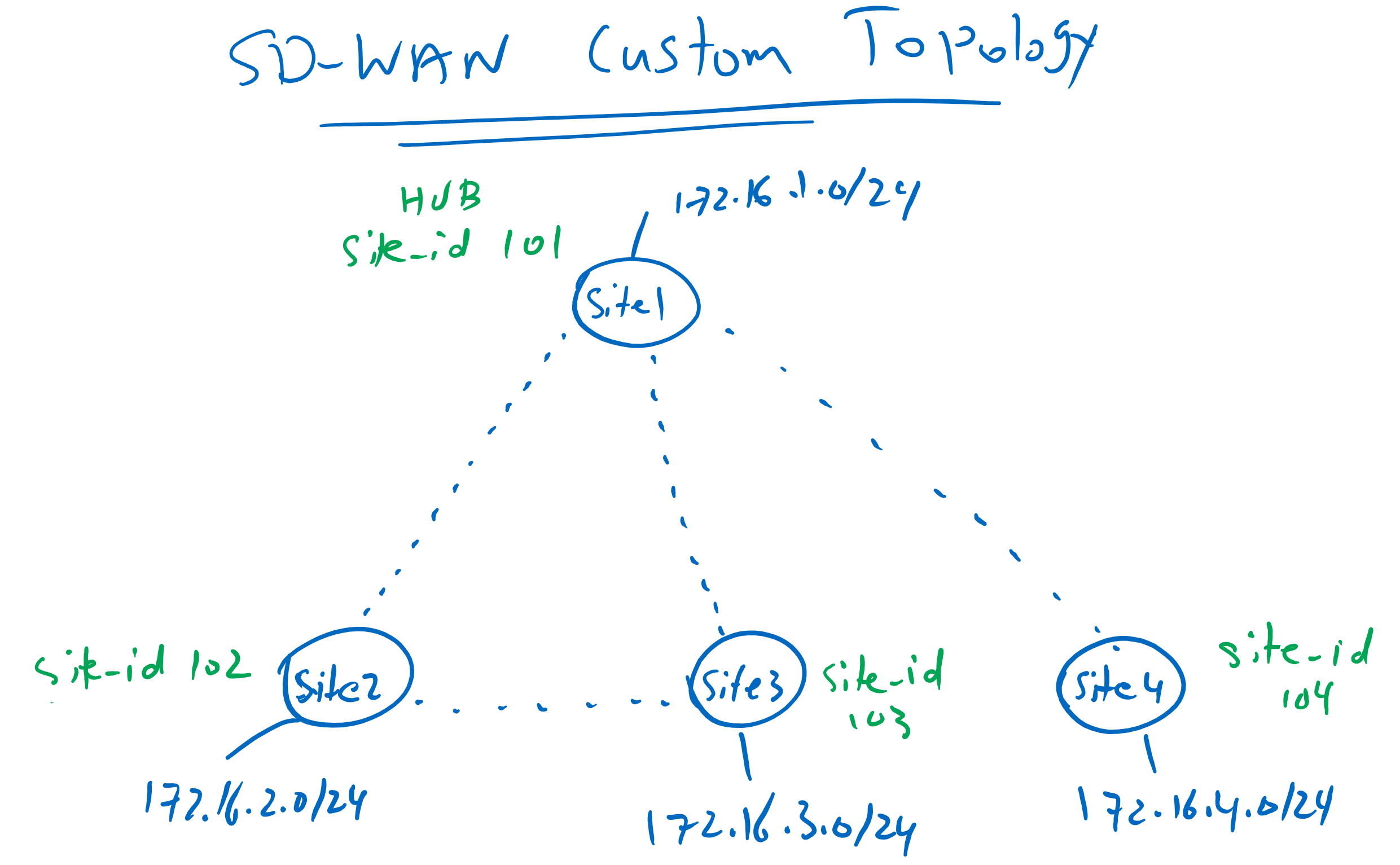
This is the topology that we will implement in this section. Site1 with site ID 101 is considered as a hub site. Spokes with site IDs from 102 to 104 can connect to each other through hub site exactly like hub-and-spoke topology. But now there is an exception, Site2 and Site3 must be able to connect directly to each other.
OMP Route Types
Just to remind you, we have two types of routes in OMP routing protocol.
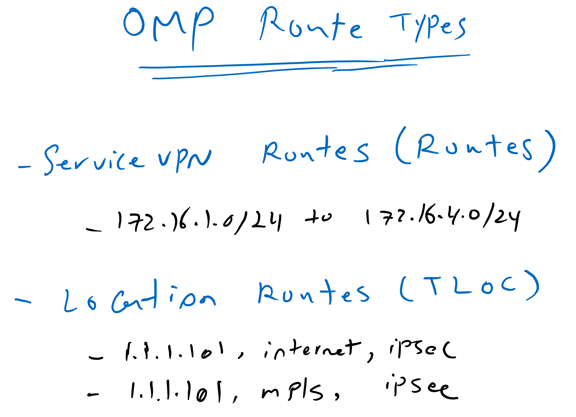
OMP Service VPN routes or simply routes that point to the services behind WAN routers. in our topology, 172.16.1.0/24 to 172.16.4.0/24 subnets are OMP routes.
and TLOCs which point to the WAN routers themselves or WAN router locations. As you may remember, TLOCs are a mixture of system IP, encapsulation type and color. in our topology, in Site1, we have two TLOCs, “1.1.1.101, public-internet, ipsec” and “1.1.1.101, mpls, ipsec”.
I have reviewed OMP route types, because we are going to manipulate these routes to create our custom topology.
SD-WAN Custom Topology with Route Manipulation
The question is how we will implement this custom topology? as you know WAN routers advertises their OMP routes and TLOCs to vSmart controller and vSmart controller reflect them to other WAN routers.

vSamrt control allow us to create our custom topology with manipulating and filtering OMP routes and TLOCs. For example, which routes and TLOCs are advertised to which sites with which preference can be easily controlled via vSmart controller. routes and TLOCs can be filtered or manipulated in vSmart controller when it receive or advertise them.
To implement this topology, nothing is changed in routes and TLOCs when they are advertised to hub site since it’s connectivity is the same with default full mesh topology.
ROUTES/SITES | Outbound to HUB | Outbound to Site4 | Outbound to Site2/Site3 |
Service Routes | No changes | Permit ALL and TLOC=HUB | Permit SITE2/SITE3/HUB Permit Site4 and TLOC=HUB |
TLOC ROUTES | No changes | Permit ONLY HUB TLOC | Permit SITE2/SITE3/HUB |
Site4 must be able to communicate with all sites but only through hub site. So all OMP routes are advertised to site4 but TLOC of the routes are changed to hub site. For more security, we advertise only hub TLOC and all other TLOCs will be filtered.
Site2 and site3 policies are different since they must be able to communicate to each other but the communication with site4 only through hub site is possible. Therefore all OMP routes are advertised to site2 and site3 but when routes belong to site4 then TLOC will be changed to hub site. For more security, we filter also site4 TLOC when it is advertised to site2 and site3.
Implement Cisco SD-WAN Custom Topology
To implement our custom topology, first we create list of sites according to common policy.
Settign -> POLICIES -> Centralized Policy -> Custom Options -> List -> Site -> New Site List
  Site List Name: SITE2_SITE3
  Add Site: 102-103

Settign -> POLICIES -> Centralized Policy -> Custom Options -> List -> Site -> New Site List
  Site List Name: SITE4
  Add Site: 104

Settign -> POLICIES -> Centralized Policy -> Custom Options -> List -> Site -> New Site List
  Site List Name: HUB_SITE2_SITE3
  Add Site: 101-103

Settign -> POLICIES -> Centralized Policy -> Custom Options -> List -> Site -> (already exist)
  Site List Name: HUB
  Add Site: 101
Then we create a TLOC for hub site since in some rule in our policy, we have to change TLOC value to hub site.
We already have created TLOC_HUB but MPLS is preferred over internet in this list. Therefore we create a new one , in which both mpls and internet have the same priority.
Settign -> POLICIES -> Centralized Policy -> Custom Options -> List -> TLOC -> New TLOC List
  List Name: HUB_LOCATION

  TLOC IP: 1.1.1.101
  Color: mpls
  Encap: ipsec

  TLOC IP: 1.1.1.101
  Color: public-internet
  Encap: ipsec
Now we need to cerate two policies, one to be applied to routes in vSmart controller when the routes are advertised to site2 and site3. The other when the route are advertised to site4.
Settign -> POLICIES -> Centralized Policy -> Custom Options -> Topology -> Add Topology -> Custom Control (Route & TLOC)
  Name: Outbound_to_Site2_Site3
  Description: Outbound_to_Site2_Site3

  Sequence Type: Route
   Sequence 1:
    Match -> Site -> Site List: HUB_SITE2_SITE3
    Action: Accept

   Sequence 2:
    Match -> Site -> Site List: SITE4
    Action: Accept & TLOC -> TLOC List: HUB_LOCATION

   Default Action:
    Reject
!
  Sequence Type: TLOC
   Sequence 1:
    Match -> Site -> Site List: HUB_SITE2_SITE3
    Action: Accept

   Default Action:
    Reject
As you can see, we have two type of routes to manipulate. “routes” and “TLOC”. We implement routes and TLOCs according to our policy.
Next we create a policy for site4.
Settign -> POLICIES -> Centralized Policy -> Custom Options -> Topology -> Add Topology -> Custom Control (Route & TLOC)
  Name: Outbound_to_Site4
  Description: Outbound_to_Site4

  Sequence Type: Route
   Sequence 1:
    Match -> Site -> Site List: HUB_SITE2_SITE3
    Action: Accept & TLOC -> TLOC List: HUB_LOCATION

   Default Action:
    Reject
!
  Sequence Type: TLOC
   Sequence 1:
    Match -> Site -> Site List: HUB
    Action: Accept

   Default Action:
    Reject
Already we have a container policy with the name vSmart-Policy. We can use the same policy and replace old mesh topology policy with our new policies.
Settign -> POLICIES -> Centralized Policy -> vSmart_Policy -> Edit -> Topology -> Add topology -> Import Existing Topology
  Custom Control (Route & TLOC): Outbound_to_Site4
  Custom Control (Route & TLOC): Outbound_to_Site2_Site3
# remove previous topology related to previous section: Mesh1
now we have to tell vSmart, which policy in which site and in which direction must be applied:
  change to Policy Application Tab -> Topology -> Outbound_to_Site2_Site3 -> New Site List
   Outbound Site List: SITE2_SITE3

  change to Policy Application Tab -> Topology -> Outbound_to_Site4 -> New Site List
   Outbound Site List: SITE4
now we can preview the commands.
viptela-policy:policy
 control-policy Outbound_to_Site2_Site3
    sequence 1
     match route
      site-list HUB_SITE2_SITE3
      prefix-list _AnyIpv4PrefixList
     !
     action accept
     !
    !
    sequence 11
     match route
      site-list SITE4
      prefix-list _AnyIpv4PrefixList
     !
     action accept
      set
       tloc-list HUB_LOCATION
      !
     !
    !
    sequence 21
     match tloc
      site-list HUB_SITE2_SITE3
     !
     action accept
     !
    !
  default-action reject
 !
 control-policy Outbound_to_Site4
    sequence 1
     match route
      site-list HUB_SITE2_SITE3
      prefix-list _AnyIpv4PrefixList
     !
     action accept
      set
       tloc-list HUB_LOCATION
      !
     !
    !
    sequence 11
     match tloc
      site-list HUB
     !
     action accept
     !
    !
  default-action reject
 !
 lists
  site-list HUB_SITE2_SITE3
   site-id 101-103
  !
  site-list SITE2_SITE3
   site-id 102-103
  !
  site-list SITE4
   site-id 104
  !
  tloc-list HUB_LOCATION
   tloc 1.1.1.101 color mpls encap ipsec
   tloc 1.1.1.101 color public-internet encap ipsec
  !
  prefix-list _AnyIpv4PrefixList
   ip-prefix 0.0.0.0/0 le 32
  !
 !
!
apply-policy
 site-list SITE4
  control-policy Outbound_to_Site4 out
 !
 site-list SITE2_SITE3
  control-policy Outbound_to_Site2_Site3 out
 !
!
In Outbound_to_Site2_Site3 policy, any prefix belonging to hub, site2 and site3 will be advertised. Any prefixes belonging to site4 will be advertised but TLOC will be changed to hub site. For security reasons, TLOCs belonging to siet2, site3 and hub will be advertised but site4 TLOC will be rejected since default action is to reject.
In Outbound_to_Site4 policy, any prefix belonging to site2, site3 and hub will be advertised but TLOC will be changed to hub site. And for security reason only TLOC belonging to hub site will be advertised and the other TLOCs will be rejected since default action is to reject.
now activate the new policy
Settign -> POLICIES -> Centralized Policy -> vSmart_Policy -> Activatecheck custom topology result
Now we can check routing table of site2 and site4 to make sure that it works as we expect.
cEdge2#show ip route vrf 10
....
Gateway of last resort is not set

      10.0.0.0/8 is variably subnetted, 3 subnets, 2 masks
m        10.1.0.1/32 [251/0] via 1.1.1.101, 2d11h
m        10.1.1.0/24 [251/0] via 1.1.1.101, 2d11h
m        10.1.2.0/24 [251/0] via 1.1.1.101, 2d11h
      172.16.0.0/16 is variably subnetted, 6 subnets, 2 masks
m        172.16.1.0/24 [251/0] via 1.1.1.101, 2d11h
C        172.16.2.0/24 is directly connected, Loopback10
L        172.16.2.1/32 is directly connected, Loopback10
m        172.16.3.0/24 [251/0] via 1.1.1.103, 2d00h
m        172.16.4.0/24 [251/0] via 1.1.1.101, 00:00:51
m        172.16.11.0/24 [251/0] via 1.1.1.101, 2d11h
site2 can connect to site3 directly. But connection with site4 , through hub site is possible since the next-hop point to system IP of hub site.
but siet4 can connect to all sites but only through hub site.
cEdge4#show ip route vrf 10
.....
Gateway of last resort is not set

      10.0.0.0/8 is variably subnetted, 3 subnets, 2 masks
m        10.1.0.1/32 [251/0] via 1.1.1.101, 00:00:19
m        10.1.1.0/24 [251/0] via 1.1.1.101, 00:00:19
m        10.1.2.0/24 [251/0] via 1.1.1.101, 00:00:19
      172.16.0.0/16 is variably subnetted, 6 subnets, 2 masks
m        172.16.1.0/24 [251/0] via 1.1.1.101, 00:00:19
m        172.16.2.0/24 [251/0] via 1.1.1.101, 00:00:20
m        172.16.3.0/24 [251/0] via 1.1.1.101, 00:00:19
C        172.16.4.0/24 is directly connected, Loopback10
L        172.16.4.1/32 is directly connected, Loopback10
m        172.16.11.0/24 [251/0] via 1.1.1.101, 00:00:19