Cisco SD-WAN Topology has a full-mesh topology by default. in other words all sites can communicate with each other without any limitation. In this section two other topologies, hub and spoke and mesh topology is implemented in cisco SD-WAN infrastructure.
Introduction to cisco SD-WAN Topology
Just to remind you, we have two types of policies in cisco SD-WAN infrastructure. localized policy that are applied directly to WAN routers and centralized policy that are applied to vSmart controller.

for topology change, centralized policy is used in cisco SD-WAN infrastructure. in other words, every topology change is implemented through the vSmart controller.
vSamrt controller can change the topology easily with filtering routes when advertising through OMP routing protocol or changing prefrence attribute.
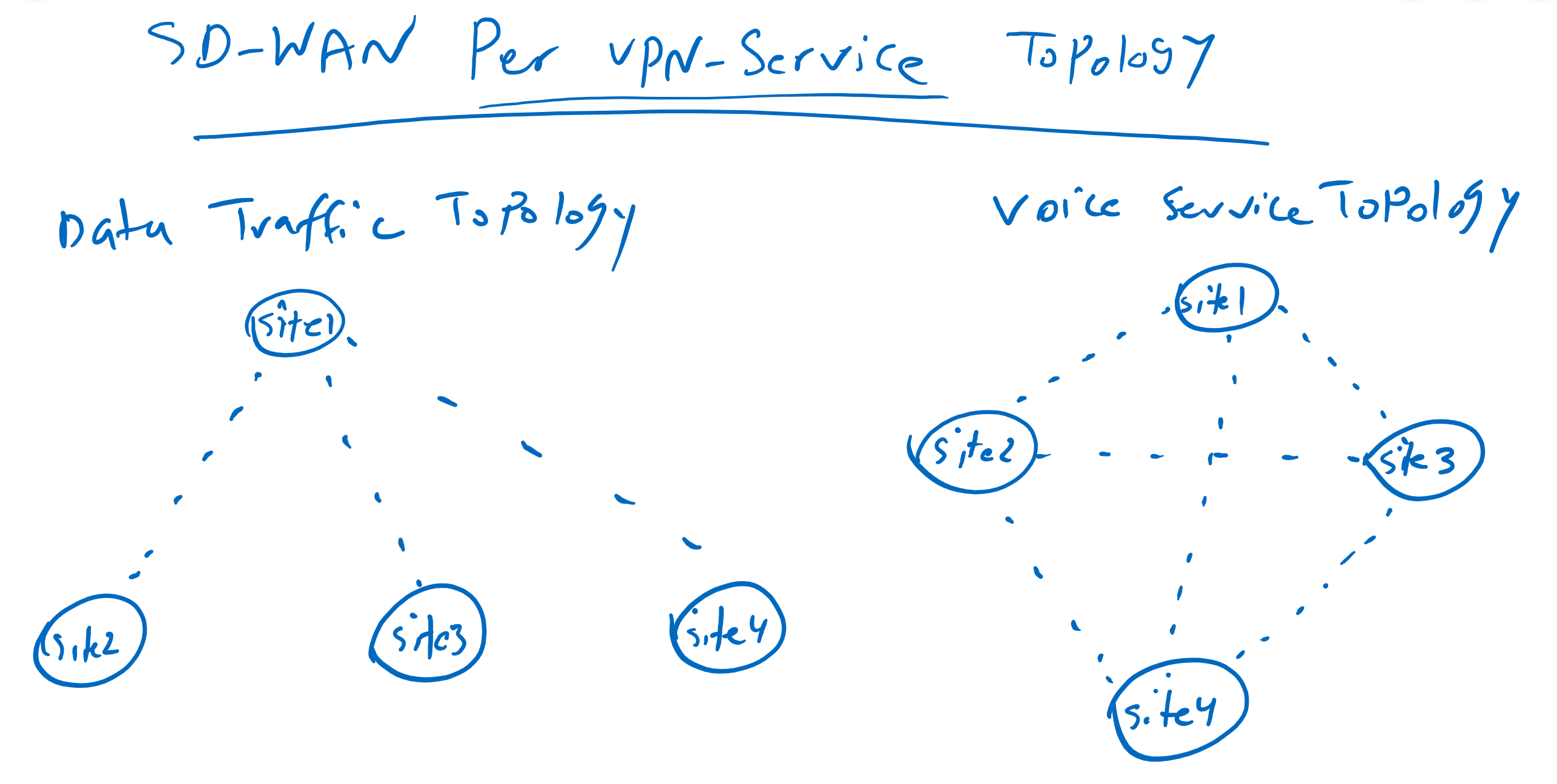
What is interesting to me when I implement different topologies in Cisco SD-WAN infrastructure, is that, topologies can be implemented per VPN service. In other words, you can, for example, implement a hub-and-spoke topology for data traffic, but at the same time implement a full-mesh topology for voice traffic. It is not easy to implement such a topology in traditional solutions.
implement hub and spoke topology
check topology status before any changes
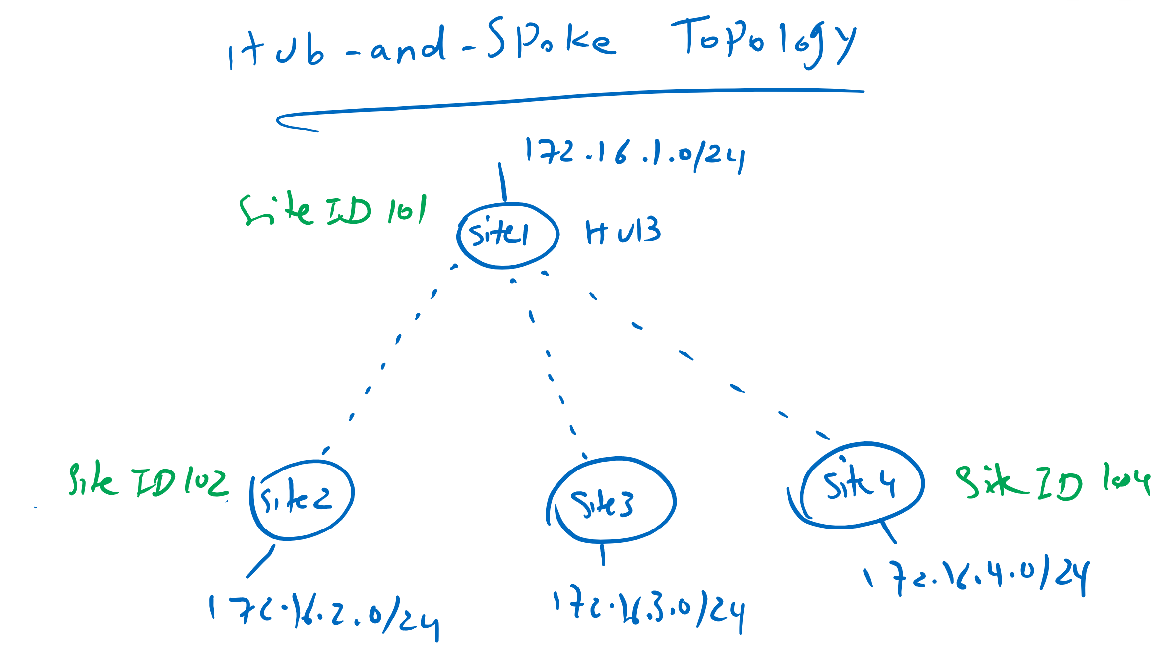
Hub-and-spoke topology is the first topology that we implement. Site1 with Site ID 101 is our hub site and other sites with Site ID 102 to 104 are spoke sites.
Before we change the topology, let’s make sure what the current topology is.
We connect to cEdge4 and then check the routing table with the command “show ip route vrf 10”.
cEdge4#show ip route vrf 10

Routing Table: 10
Codes: L - local, C - connected, S - static, R - RIP, M - mobile, B - BGP
       D - EIGRP, EX - EIGRP external, O - OSPF, IA - OSPF inter area
       N1 - OSPF NSSA external type 1, N2 - OSPF NSSA external type 2
       E1 - OSPF external type 1, E2 - OSPF external type 2, m - OMP
       n - NAT, Ni - NAT inside, No - NAT outside, Nd - NAT DIA
       i - IS-IS, su - IS-IS summary, L1 - IS-IS level-1, L2 - IS-IS level-2
       ia - IS-IS inter area, * - candidate default, U - per-user static route
       H - NHRP, G - NHRP registered, g - NHRP registration summary
       o - ODR, P - periodic downloaded static route, l - LISP
       a - application route
       + - replicated route, % - next hop override, p - overrides from PfR

Gateway of last resort is not set

      10.0.0.0/8 is variably subnetted, 3 subnets, 2 masks
m        10.1.0.1/32 [251/0] via 1.1.1.101, 00:32:45
m        10.1.1.0/24 [251/0] via 1.1.1.101, 00:32:45
m        10.1.2.0/24 [251/0] via 1.1.1.101, 00:32:45
      172.16.0.0/16 is variably subnetted, 6 subnets, 2 masks
m        172.16.1.0/24 [251/0] via 1.1.1.101, 00:32:45
m        172.16.2.0/24 [251/0] via 1.1.1.102, 00:32:45
m        172.16.3.0/24 [251/0] via 1.1.1.103, 00:34:35
C        172.16.4.0/24 is directly connected, Loopback10
L        172.16.4.1/32 is directly connected, Loopback10
m        172.16.11.0/24 [251/0] via 1.1.1.101, 00:32:45
As you can see, next hop address points to the system IP of destination site itself.
We can also check the connectivity with the traceroute command.
cEdge4#traceroute vrf 10 172.16.3.1 source 172.16.4.1
Type escape sequence to abort.
Tracing the route to 172.16.3.1
VRF info: (vrf in name/id, vrf out name/id)
  1 172.16.3.1 2 msec 1 msec *
cEdge4#
Since we have two transports between sites, the question is, which transport is used to route the traffic between sites. With the command “show sdwan omp route” we can check the OMP routing table with further details.
cEdge4#show sdwan omp routes
....
---------------------------------------------------
omp route entries for vpn 10 route 172.16.3.0/24
---------------------------------------------------
            RECEIVED FROM:
peer            1.1.1.52
path-id         1
label           1001
status          C,I,R
loss-reason     not set
lost-to-peer    not set
lost-to-path-id not set
    Attributes:
     originator       1.1.1.103
     type             installed
     tloc             1.1.1.103, mpls, ipsec
     ultimate-tloc    not set
     domain-id        not set
     overlay-id        1
     site-id          103
     preference       not set
     tag              not set
     origin-proto     connected
     origin-metric    0
     as-path          not set
     unknown-attr-len not set
            RECEIVED FROM:
peer            1.1.1.52
path-id         2
label           1001
status          C,I,R
loss-reason     not set
lost-to-peer    not set
lost-to-path-id not set
    Attributes:
     originator       1.1.1.103
     type             installed
     tloc             1.1.1.103, public-internet, ipsec
     ultimate-tloc    not set
     domain-id        not set
     overlay-id        1
     site-id          103
     preference       not set
     tag              not set
     origin-proto     connected
     origin-metric    0
     as-path          not set
     unknown-attr-len not set
....
For example, if we check the detail for site3 (172.16.3.0/24), you can see that there are two paths with two tlocs in which traffic is routed. One through ipsec/mpls and the other through ipsec/internet. and both paths have the same preference. So we can expect the traffic to be shared between these two paths.
To make sure, we can also check it with command “show sdwan ip fib vpn 10”.
cEdge4#show sdwan ip fib vpn 10
                                             NEXTHOP     NEXTHOP          NEXTHOP  SA
VPN  PREFIX                                  IF NAME     ADDR             LABEL    INDEX    TLOC IP          COLOR
------------------------------------------------------------------------------------------------------------------------------
10   10.1.0.1/32                             ipsec       192.168.2.101    1001     17       1.1.1.101        mpls
10   10.1.0.1/32                             ipsec       192.168.2.101    1001     18       1.1.1.101        mpls
10   10.1.0.1/32                             ipsec       192.168.1.101    1001     19       1.1.1.101        public-internet
10   10.1.0.1/32                             ipsec       192.168.1.101    1001     20       1.1.1.101        public-internet
10   10.1.1.0/24                             ipsec       192.168.2.101    1001     17       1.1.1.101        mpls
10   10.1.1.0/24                             ipsec       192.168.2.101    1001     18       1.1.1.101        mpls
10   10.1.1.0/24                             ipsec       192.168.1.101    1001     19       1.1.1.101        public-internet
10   10.1.1.0/24                             ipsec       192.168.1.101    1001     20       1.1.1.101        public-internet
10   10.1.2.0/24                             ipsec       192.168.2.101    1001     17       1.1.1.101        mpls
10   10.1.2.0/24                             ipsec       192.168.2.101    1001     18       1.1.1.101        mpls
10   10.1.2.0/24                             ipsec       192.168.1.101    1001     19       1.1.1.101        public-internet
10   10.1.2.0/24                             ipsec       192.168.1.101    1001     20       1.1.1.101        public-internet
10   172.16.1.0/24                           ipsec       192.168.2.101    1001     17       1.1.1.101        mpls
10   172.16.1.0/24                           ipsec       192.168.2.101    1001     18       1.1.1.101        mpls
10   172.16.1.0/24                           ipsec       192.168.1.101    1001     19       1.1.1.101        public-internet
10   172.16.1.0/24                           ipsec       192.168.1.101    1001     20       1.1.1.101        public-internet
10   172.16.2.0/24                           ipsec       192.168.1.102    1001     21       1.1.1.102        public-internet
10   172.16.2.0/24                           ipsec       192.168.1.102    1001     22       1.1.1.102        public-internet
10   172.16.2.0/24                           ipsec       192.168.2.102    1001     23       1.1.1.102        mpls
10   172.16.2.0/24                           ipsec       192.168.2.102    1001     24       1.1.1.102        mpls
10   172.16.3.0/24                           ipsec       192.168.1.103    1001     13       1.1.1.103        public-internet
10   172.16.3.0/24                           ipsec       192.168.1.103    1001     14       1.1.1.103        public-internet
10   172.16.3.0/24                           ipsec       192.168.2.103    1001     15       1.1.1.103        mpls
10   172.16.3.0/24                           ipsec       192.168.2.103    1001     16       1.1.1.103        mpls
10   172.16.11.0/24                          ipsec       192.168.2.101    1001     17       1.1.1.101        mpls
10   172.16.11.0/24                          ipsec       192.168.2.101    1001     18       1.1.1.101        mpls
10   172.16.11.0/24                          ipsec       192.168.1.101    1001     19       1.1.1.101        public-internet
10   172.16.11.0/24                          ipsec       192.168.1.101    1001     20       1.1.1.101        public-internet
As you can see there are four path to reach destination site3 (172.16.3.0/24). Two over public-internet transport and two over mpls transport. from mpls transport to internet transport, from internet to internet, from mpls to mpls and from internet to mpls transport.
configure hub and spoke topology
Now we can start changing topology for VPN10 service traffic. However, this is the only VPN service that we have implemented in our topology, but it is important to know that topology changes are possible per service VPN.
Topology changes are configured through a centralized policy. In other words, all configurations are implemented in vSmart controller. When vSamrt controller learns or advertises routes through OMP, it can control which routes to which sites are advertised with which preference.

First, let’s specify to vManage, which site is our hub site and which are spoke sites.
CONFIGURATION -> POLICIES -> centralized Policy -> custom options -> Site -> New Site List

Site List Name: HUB
Add Site: 101

CONFIGURATION -> POLICIES -> centralized Policy -> custom options -> Site -> New Site List

Site List Name: SPOKES
Add Site: 102-104
Then we specify service VPN number in which we change the topology.
CONFIGURATION -> POLICIES -> centralized Policy -> custom options -> VPN -> New VPN List

VPN List Name: VPN10
Add VPN: 10
Then we specify our interesting topology.
CONFIGURATION -> POLICIES -> centralized Policy -> custom options -> topology -> Add Topology -> Hub-and-Spoke

Name: Hub-and-Spoke
Description: Hub-and-Spoke
VPN List: VPN10 (defined above)
Add Hub Site: Site List=HUB (defined above)
Add Spoke Sites: Site List= SPOKES (defined above)
Now we have to specify a container policy. As in the previous section explained. Container policy is just a container for policies of any type. Container policy is required, since it is the only policy that can be applied to vSamrt controller.
We create a new one with the name of vSamrt_Policy since this policy must be applied to vSamrt controller.
CONFIGURATION -> POLICIES -> centralized Policy -> Add Policy -> section: Configure Topology and VPN Membership

  Policy Name: vSmart_Policy
  Policy Description : vSmart_Policy
  Import : Hub-and-Spoke
With preview, we can check the configuration that will be applied to vSmart controller.
viptela-policy:policy
 control-policy control_2008914673
    sequence 10
     match route
      site-list HUB
      vpn-list VN10
     !
     action accept
     !
    !
    sequence 20
     match tloc
      site-list HUB
     !
     action accept
     !
    !
  default-action reject
 !
 lists
  site-list HUB
   site-id 101
  !
  site-list SPOKES
   site-id 102-104
  !
  vpn-list VN10
   vpn 10
  !
 !
!
apply-policy
 site-list SPOKES
  control-policy control_2008914673 out
As we can see in the output command, the policy is applied only when routes are advertised to spokes thorugh vSamrt controller. The policy states that routes will only be advertised to spoke routers if they belong to the hub site and VPN10 service VPN. This is also true for tloc routes. Tloc routes are only advertised to spoke sites if they belong to Hub-Site. The other routes are rejected by default.
With this policy, spoke sites can not communicate to each other and the communication only with hub site is only possible.
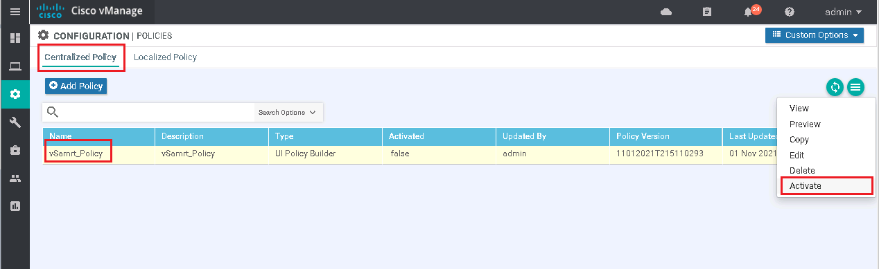
Next we have to activate our policy as follows.
Again we can check vrf 10 routing table in cEdge4 with “show ip route vrf 10”. As we expect, there is no more any routes in cEdge4 router except the routes belonging to hub site.
cEdge4#show ip route vrf 10

Routing Table: 10
Codes: L - local, C - connected, S - static, R - RIP, M - mobile, B - BGP
       D - EIGRP, EX - EIGRP external, O - OSPF, IA - OSPF inter area
       N1 - OSPF NSSA external type 1, N2 - OSPF NSSA external type 2
       E1 - OSPF external type 1, E2 - OSPF external type 2, m - OMP
       n - NAT, Ni - NAT inside, No - NAT outside, Nd - NAT DIA
       i - IS-IS, su - IS-IS summary, L1 - IS-IS level-1, L2 - IS-IS level-2
       ia - IS-IS inter area, * - candidate default, U - per-user static route
       H - NHRP, G - NHRP registered, g - NHRP registration summary
       o - ODR, P - periodic downloaded static route, l - LISP
       a - application route
       + - replicated route, % - next hop override, p - overrides from PfR

Gateway of last resort is not set

      10.0.0.0/8 is variably subnetted, 3 subnets, 2 masks
m        10.1.0.1/32 [251/0] via 1.1.1.101, 07:10:11
m        10.1.1.0/24 [251/0] via 1.1.1.101, 07:10:11
m        10.1.2.0/24 [251/0] via 1.1.1.101, 07:10:11
      172.16.0.0/16 is variably subnetted, 4 subnets, 2 masks
m        172.16.1.0/24 [251/0] via 1.1.1.101, 07:10:11
C        172.16.4.0/24 is directly connected, Loopback10
L        172.16.4.1/32 is directly connected, Loopback10
m        172.16.11.0/24 [251/0] via 1.1.1.101, 07:10:11
cEdge4#
So the communication will not be possible any more between spoke sites. But with hub , the communication is still possible.
cEdge4#traceroute vrf 10 172.16.3.1 source 172.16.4.1
Type escape sequence to abort.
Tracing the route to 172.16.3.1
VRF info: (vrf in name/id, vrf out name/id)
  1  *  *  *
  2  *  *  *
  3
cEdge4#
cEdge4#traceroute vrf 10 172.16.1.1 source 172.16.4.1
Type escape sequence to abort.
Tracing the route to 172.16.1.1
VRF info: (vrf in name/id, vrf out name/id)
  1 172.16.1.1 462 msec *  5 msec
cEdge4#
configure WAN Transport Prefrence
Still, there are two questions in this topology. First, how can I prefer mpls transport to internet transport for the communication between sites.. Second, how spoke sites can communicate to each other, but through hub site and not directly.
To answer these two questions, lets’ edit our policy. First, we need to differentiate between mpls and internet transport by setting the tloc preference. we set preference 200 for mpls tloc and preference 150 for internet tloc.
CONFIGURATION -> POLICIES -> centralized Policy -> custom options -> TLOC -> New TLOC List

List Name: HUB_TLOC
TLOC IP: 1.1.1.101
Color: mpls
Encap: ipsec
Preference: 200

TLOC IP: 1.1.1.101
Color: public-internet
Encap: ipsec
Preference: 150
Then we apply the new preference in our Hub-and-Spoke policy.
CONFIGURATION -> POLICIES -> centralized Policy -> custom options -> topology -> Hub-and-Spoke -> Edit

Section: Hub preferences -> manage custom preferences and prefix Lists
All Hubs are equal: unselect (clear)
Advertise HUB TLOCs: HUB_TLOC (defined above)
Now we can save and activate our new policy and then preview vSmart controller new commands.
policy
 lists
  vpn-list VN10
   vpn 10
  !
  tloc-list HUB_TLOC
   tloc 1.1.1.101 color mpls encap ipsec preference 200
   tloc 1.1.1.101 color public-internet encap ipsec preference 150
  !
  site-list HUB
   site-id 101
  !
  site-list SPOKES
   site-id 102-104
  !
 !
 control-policy control_-707752447
  sequence 10
   match route
    site-list HUB
    vpn-list  VN10
   !
   action accept
   !
  !
  sequence 20
   match route
    site-list SPOKES
    vpn-list  VN10
   !
   action accept
    set
     tloc-list HUB_TLOC
    !
   !
  !
  sequence 30
   match tloc
    site-list HUB
   !
   action accept
    set
     preference 20
    !
   !
  !
  default-action reject
 !
!
apply-policy
 site-list SPOKES
  control-policy control_-707752447 out
In new policies, spokes routes are not rejected any more but their tloc is changed to Hub_TLOC preference that we have already configured. It means, first, communication between spokes are through hub site. Second, according to pre-defined preference, traffic will be forwarded preferably through mpls transport.
As you can see, only hub tloc is advertised through vSmart controller to spoke routers and other tloc will be rejected by vSmart controller.
With “show ip route vrf 10” in cEdge4, we can check what is the new changes in routing table.
cEdge4#show ip route vrf 10

Routing Table: 10
Codes: L - local, C - connected, S - static, R - RIP, M - mobile, B - BGP
       D - EIGRP, EX - EIGRP external, O - OSPF, IA - OSPF inter area
       N1 - OSPF NSSA external type 1, N2 - OSPF NSSA external type 2
       E1 - OSPF external type 1, E2 - OSPF external type 2, m - OMP
       n - NAT, Ni - NAT inside, No - NAT outside, Nd - NAT DIA
       i - IS-IS, su - IS-IS summary, L1 - IS-IS level-1, L2 - IS-IS level-2
       ia - IS-IS inter area, * - candidate default, U - per-user static route
       H - NHRP, G - NHRP registered, g - NHRP registration summary
       o - ODR, P - periodic downloaded static route, l - LISP
       a - application route
       + - replicated route, % - next hop override, p - overrides from PfR

Gateway of last resort is not set

      10.0.0.0/8 is variably subnetted, 3 subnets, 2 masks
m        10.1.0.1/32 [251/0] via 1.1.1.101, 00:00:15
m        10.1.1.0/24 [251/0] via 1.1.1.101, 00:00:15
m        10.1.2.0/24 [251/0] via 1.1.1.101, 00:00:15
      172.16.0.0/16 is variably subnetted, 6 subnets, 2 masks
m        172.16.1.0/24 [251/0] via 1.1.1.101, 00:00:15
m        172.16.2.0/24 [251/0] via 1.1.1.101, 00:00:15
m        172.16.3.0/24 [251/0] via 1.1.1.101, 00:00:15
C        172.16.4.0/24 is directly connected, Loopback10
L        172.16.4.1/32 is directly connected, Loopback10
m        172.16.11.0/24 [251/0] via 1.1.1.101, 00:00:15
cEdge4#
As you can see, spoke routes are not discarded any more and they cen be seen in routing table. And if we notice, we see that next-hop address of all spoke routes point to hub site. It means. Communication between spoke site will be forwarded through hub site
With “show sdwan omp route” and “show sdwan ip fib vpn 10”, we can confirm that mpls transport is preferred over internet transport.
cEdge4#show sdwan omp routes
....
---------------------------------------------------
omp route entries for vpn 10 route 172.16.3.0/24
---------------------------------------------------
            RECEIVED FROM:
peer            1.1.1.52
path-id         20
label           1001
status          C,I,R
loss-reason     not set
lost-to-peer    not set
lost-to-path-id not set
    Attributes:
     originator       1.1.1.103
     type             installed
     tloc             1.1.1.101, mpls, ipsec
     ultimate-tloc    not set
     domain-id        not set
     overlay-id        1
     site-id          103
     preference       200
     tag              not set
     origin-proto     connected
     origin-metric    0
     as-path          not set
     unknown-attr-len not set
            RECEIVED FROM:
peer            1.1.1.52
path-id         21
label           1001
status          R
loss-reason     preference
lost-to-peer    1.1.1.52
lost-to-path-id 20
    Attributes:
     originator       1.1.1.103
     type             installed
     tloc             1.1.1.101, public-internet, ipsec
     ultimate-tloc    not set
     domain-id        not set
     overlay-id        1
     site-id          103
     preference       150
     tag              not set
     origin-proto     connected
     origin-metric    0
     as-path          not set
     unknown-attr-len not set
....cEdge4#show sdwan ip fib vpn 10
NEXTHOP NEXTHOP NEXTHOP SA
VPN PREFIX IF NAME ADDR LABEL INDEX TLOC IP COLOR
------------------------------------------------------------------------------------------------------------------------------
10 10.1.0.1/32 ipsec 192.168.2.101 1001 2 1.1.1.101 mpls
10 10.1.0.1/32 ipsec 192.168.2.101 1001 8 1.1.1.101 mpls
10 10.1.0.1/32 ipsec 192.168.1.101 1001 1 1.1.1.101 public-internet
10 10.1.0.1/32 ipsec 192.168.1.101 1001 7 1.1.1.101 public-internet
10 10.1.1.0/24 ipsec 192.168.2.101 1001 2 1.1.1.101 mpls
10 10.1.1.0/24 ipsec 192.168.2.101 1001 8 1.1.1.101 mpls
10 10.1.1.0/24 ipsec 192.168.1.101 1001 1 1.1.1.101 public-internet
10 10.1.1.0/24 ipsec 192.168.1.101 1001 7 1.1.1.101 public-internet
10 10.1.2.0/24 ipsec 192.168.2.101 1001 2 1.1.1.101 mpls
10 10.1.2.0/24 ipsec 192.168.2.101 1001 8 1.1.1.101 mpls
10 10.1.2.0/24 ipsec 192.168.1.101 1001 1 1.1.1.101 public-internet
10 10.1.2.0/24 ipsec 192.168.1.101 1001 7 1.1.1.101 public-internet
10 172.16.1.0/24 ipsec 192.168.2.101 1001 2 1.1.1.101 mpls
10 172.16.1.0/24 ipsec 192.168.2.101 1001 8 1.1.1.101 mpls
10 172.16.1.0/24 ipsec 192.168.1.101 1001 1 1.1.1.101 public-internet
10 172.16.1.0/24 ipsec 192.168.1.101 1001 7 1.1.1.101 public-internet
10 172.16.2.0/24 ipsec 192.168.2.101 1001 2 1.1.1.101 mpls
10 172.16.2.0/24 ipsec 192.168.2.101 1001 8 1.1.1.101 mpls
10 172.16.3.0/24 ipsec 192.168.2.101 1001 2 1.1.1.101 mpls
10 172.16.3.0/24 ipsec 192.168.2.101 1001 8 1.1.1.101 mpls
10 172.16.11.0/24 ipsec 192.168.2.101 1001 2 1.1.1.101 mpls
10 172.16.11.0/24 ipsec 192.168.2.101 1001 8 1.1.1.101 mpls
10 172.16.11.0/24 ipsec 192.168.1.101 1001 1 1.1.1.101 public-internet
10 172.16.11.0/24 ipsec 192.168.1.101 1001 7 1.1.1.101 public-internetIt can be checked easily with traceroute command.
cEdge4#traceroute vrf 10 172.16.3.1 source 172.16.4.1
Type escape sequence to abort.
Tracing the route to 172.16.3.1
VRF info: (vrf in name/id, vrf out name/id)
  1 192.168.2.101 122 msec 1 msec 2 msec
  2 172.16.3.1 221 msec *  2 msec
cEdge4#
As you can see, traffic to site3 (172.16.3.0/24) is routed through hub over both transport. but mpls preference is 200 and internet transport preference is 150.
Confugre Mesh topology
In the next scenario, we implement a mesh topology.
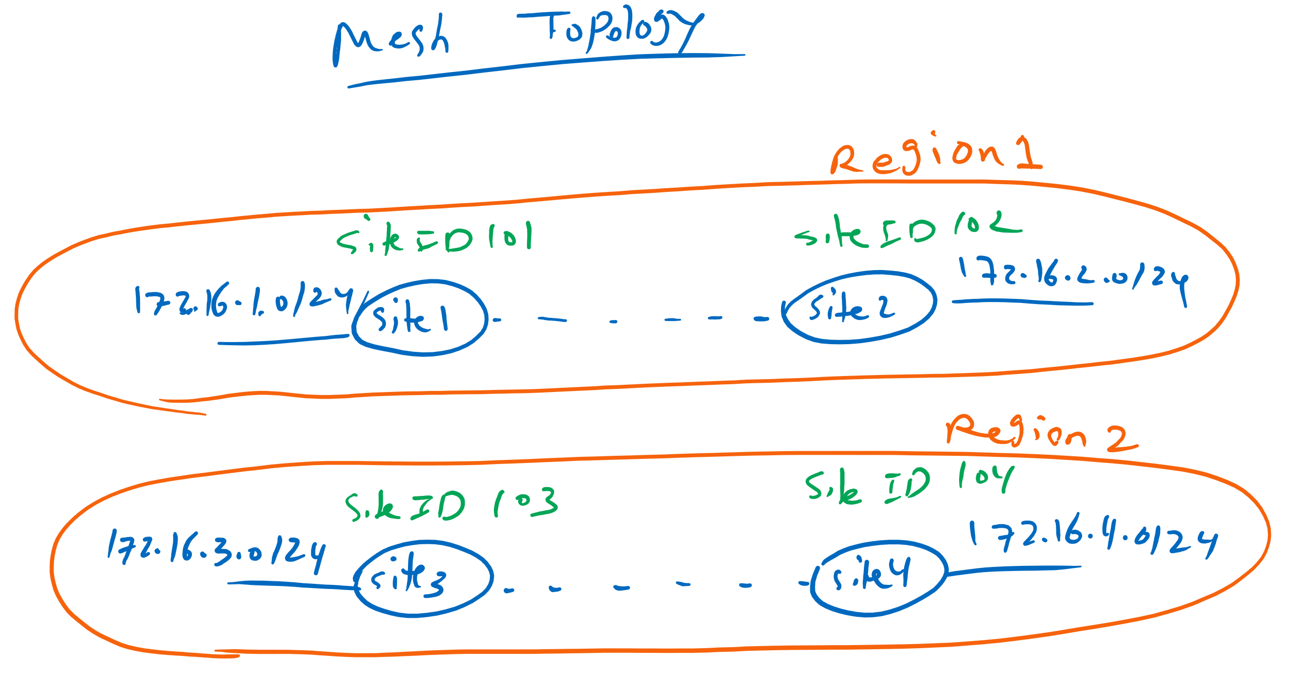
in this new topology, site1 and site2 will be in the same region, Region1. site3 and site4 also will be in another region, Region2. Only sites in the same region can communicate to each other and there is not communication between sites in different region.
First, we have to define our regions and specify which sites belong to each region.
CONFIGURATION -> POLICIES -> centralized Policy -> custom options -> Site -> New Site List
Site List Name: Region1
Add Site: 101-102

CONFIGURATION -> POLICIES -> centralized Policy -> custom options -> Site -> New Site List
Site List Name: Region2
Add Site: 103-104
Then we create a new topology.
CONFIGURATION -> POLICIES -> centralized Policy -> custom options -> topology -> Add Topology -> Mesh

Name: Mesh1
Description: Mesh1
VPN List: VPN10 (defined before)
Add:
Mesh Region Name: Region1
Site List: Region1 (defined above)
Add:
Mesh Region Name: Region2
Site List: Region2 (defined above)
Now we replace hub and spoke topology with this new mesh topology.
CONFIGURATION -> POLICIES -> centralized Policy -> vSmart_Policy -> Edit -> Topology -> Import Existing Topology -> Mesh -> Mesh1 -> import
!
CONFIGURATION -> POLICIES -> centralized Policy -> vSmart_Policy -> Edit -> Topology -> Hub-and-Spoke -> Detach
Now we can check preview commands.
viptela-policy:policy
 control-policy control_2066904353
    sequence 10
     match route
      site-list Region2
      vpn-list VN10
     !
     action accept
     !
    !
    sequence 20
     match tloc
      site-list Region2
     !
     action accept
     !
    !
  default-action reject
 !
 control-policy control_1530727231
    sequence 10
     match route
      site-list Region1
      vpn-list VN10
     !
     action accept
     !
    !
    sequence 20
     match tloc
      site-list Region1
     !
     action accept
     !
    !
  default-action reject
 !
 lists
  site-list Region1
   site-id 101-102
  !
  site-list Region2
   site-id 103-104
  !
  vpn-list VN10
   vpn 10
  !
 !
!
apply-policy
 site-list Region2
  control-policy control_2066904353 out
 !
 site-list Region1
  control-policy control_1530727231 out
Now two policies are created. One for sites in Region1 and the other for sites belonging to Region2. In each policies only routes belonging to the same region are advertised and the others are discarded.
Now we expect that site4 is only able to communicate with site3. And it is not able to communicate with site1 and site2. We can check it easily with “show ip route vrf 10”
cEdge4#show ip route vrf 10

Routing Table: 10
Codes: L - local, C - connected, S - static, R - RIP, M - mobile, B - BGP
       D - EIGRP, EX - EIGRP external, O - OSPF, IA - OSPF inter area
       N1 - OSPF NSSA external type 1, N2 - OSPF NSSA external type 2
       E1 - OSPF external type 1, E2 - OSPF external type 2, m - OMP
       n - NAT, Ni - NAT inside, No - NAT outside, Nd - NAT DIA
       i - IS-IS, su - IS-IS summary, L1 - IS-IS level-1, L2 - IS-IS level-2
       ia - IS-IS inter area, * - candidate default, U - per-user static route
       H - NHRP, G - NHRP registered, g - NHRP registration summary
       o - ODR, P - periodic downloaded static route, l - LISP
       a - application route
       + - replicated route, % - next hop override, p - overrides from PfR

Gateway of last resort is not set

      172.16.0.0/16 is variably subnetted, 3 subnets, 2 masks
m        172.16.3.0/24 [251/0] via 1.1.1.103, 00:00:39
C        172.16.4.0/24 is directly connected, Loopback10
L        172.16.4.1/32 is directly connected, Loopback10