Cisco SD-WAN non-direct internet access is the discussion of this section. non-direct internet access means tunnelling branch Internet traffic to a central site or datacenter for Internet access.
Cisco SD-WAN direct Internet Access will be discussed in another section.
Topology Overview
This is our topology for transmitting Internet access to branches through SD-WAN IPSec tunnel infrastructure.
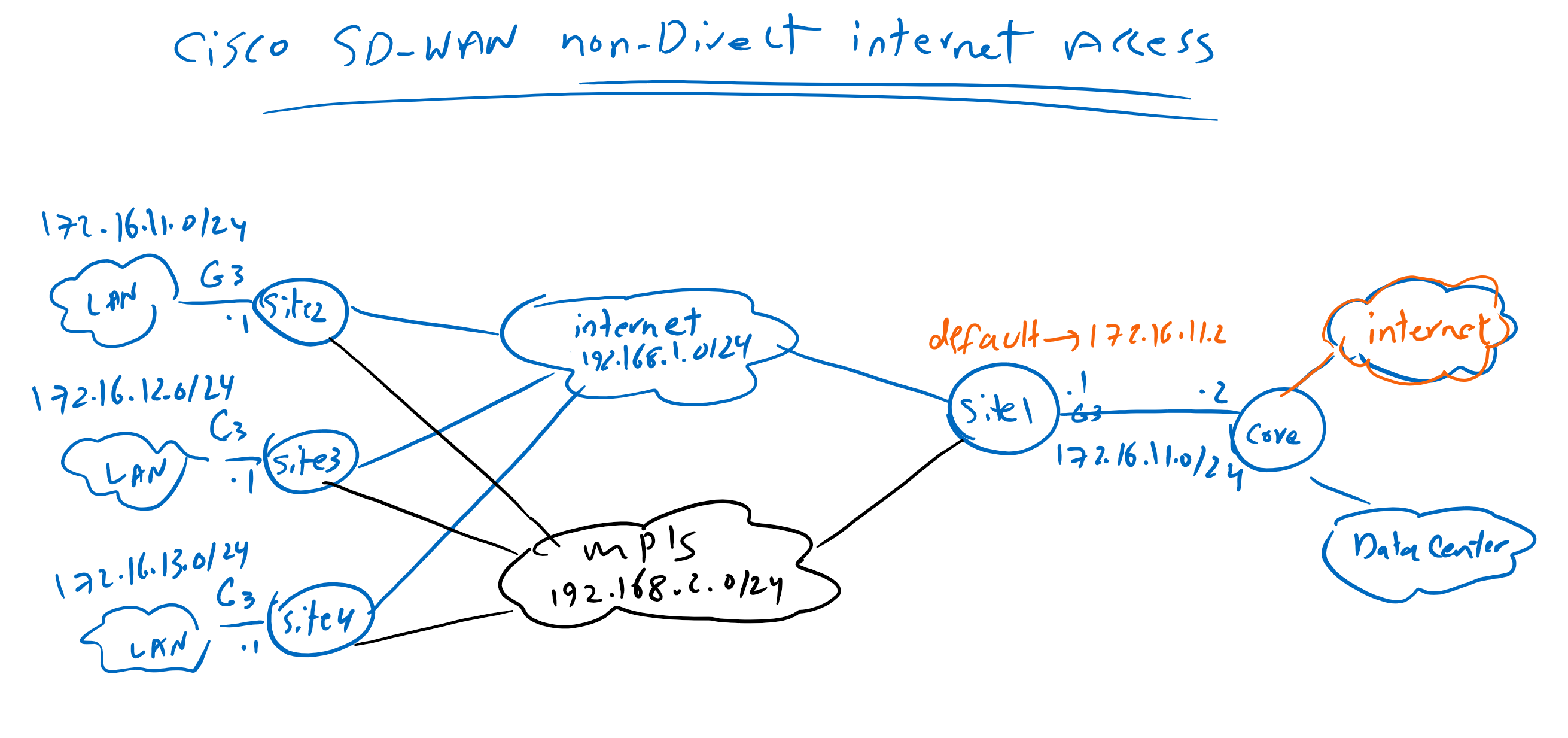
Site1 is already connected to datacenter through Gigabitethernet3 which we have implemented in the section “14. OSPF in Service VPN in Cisco SD-WAN”. Suppose internet is also accessible through the same link. so only a default route must be added in site1 router in the same direction as datacenter to bring internet connectivity in Site1 Service VPN.
Then the target is to transfer internet access to branches in site2 to site4.
After bringing internet access in branches, we will create a new LAN interface, GigabitEthernet3, in branch offices just like Site1. So we can check if internet is accessible through the computers behind this new interface. The IP subnet for the new LAN interface are 172.16.12.0/24 in siet2 to 172.16.14.0/24 in site4.
non-direct internet access configuration
add default route in site1
First we create a default route in existing VPN 10 feature template and apply it to site1. With adding default route in site1, we bring internet access in site1 and then default route can be advertised to other branches through OMP routing protocol.
Feature template with the name CSR1000v_VPN10_cEdge1 is already applied to site1 so we edit this feature template to add a default route in site1.
CONFIGURATION ->  TEMPLATES -> Feature Template
 Template Name: CSR1000v_VPN10_cEdge1
 Section: IPv4 ROUTE
# New IPv4 Route
 Prefix: 0.0.0.0/0
 Next Hop: 172.16.11.2
If we preview the new configuration, we see that just a default route is added in in VRF 10.
ip route vrf 10 0.0.0.0 0.0.0.0 172.16.11.2After applying the configuration, we can check site1 vrf 10 routing table to make sure that default route exist.
cEdge1#show ip route vrf 10
....
Gateway of last resort is 172.16.11.2 to network 0.0.0.0

S*    0.0.0.0/0 [1/0] via 172.16.11.2
      10.0.0.0/8 is variably subnetted, 3 subnets, 2 masks
O        10.1.0.1/32 [110/2] via 172.16.11.2, 5d20h, GigabitEthernet3
O E2     10.1.1.0/24 [110/20] via 172.16.11.2, 5d20h, GigabitEthernet3
S        10.1.2.0/24 [1/0] via 172.16.11.2
      172.16.0.0/16 is variably subnetted, 7 subnets, 2 masks
C        172.16.1.0/24 is directly connected, Loopback10
L        172.16.1.1/32 is directly connected, Loopback10
m        172.16.2.0/24 [251/0] via 1.1.1.102, 5d20h
m        172.16.3.0/24 [251/0] via 1.1.1.103, 1d01h
m        172.16.4.0/24 [251/0] via 1.1.1.104, 1d01h
C        172.16.11.0/24 is directly connected, GigabitEthernet3
L        172.16.11.1/32 is directly connected, GigabitEthernet3
With ping command, also we check if site1 has internet connectivity through VRF 10 service VPN.
cEdge1#ping vrf 10 8.8.8.8
Type escape sequence to abort.
Sending 5, 100-byte ICMP Echos to 8.8.8.8, timeout is 2 seconds:
!!!!!
Success rate is 100 percent (5/5), round-trip min/avg/max = 63/67/76 ms
cEdge1#
advertise default route to branches
You may remember that static routes, by default, are advertised in OMP.
In any case, we have already created an OMP policy in Service VPN section to advertise static and internal and external OSPF routes via OMP routing protocol.
We can review this policy to make sure our new default static route is propagated to other branches.
CONFIGURATION ->  TEMPLATES -> Feature Template
 Template Name: CSR1000v_OMP
 Section: Advertise
 Static: On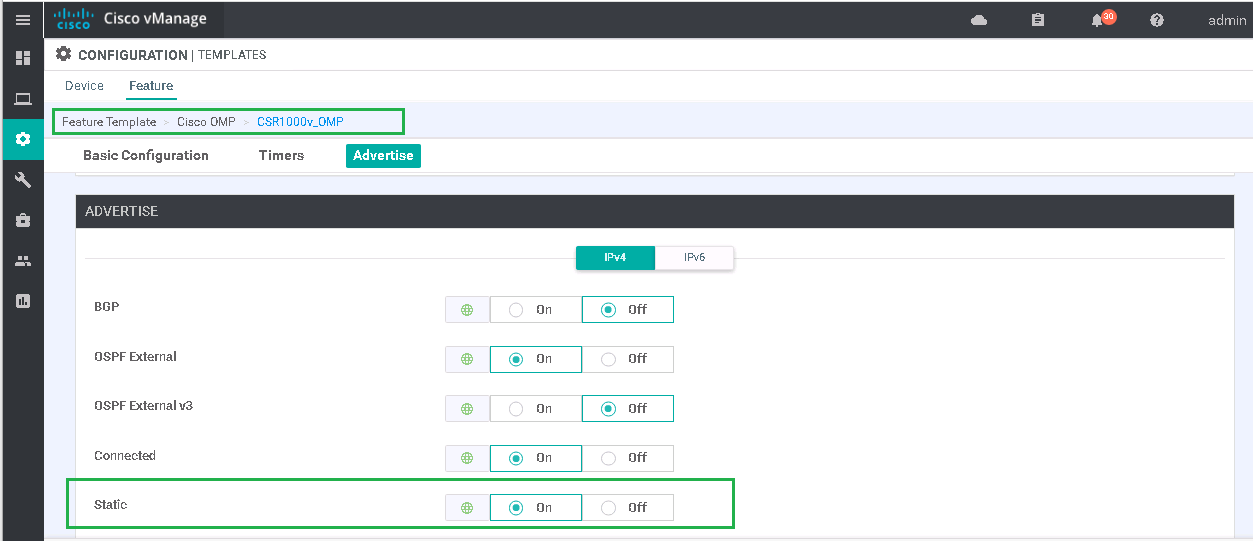
We can also check VRF 10 routing table of other edge routers to make sure if default route now exist.
cEdge4#show ip route vrf 10

....

Gateway of last resort is 1.1.1.101 to network 0.0.0.0

m*    0.0.0.0/0 [251/0] via 1.1.1.101, 01:12:27
      10.0.0.0/8 is variably subnetted, 3 subnets, 2 masks
m        10.1.0.1/32 [251/0] via 1.1.1.101, 1d01h
m        10.1.1.0/24 [251/0] via 1.1.1.101, 1d01h
m        10.1.2.0/24 [251/0] via 1.1.1.101, 1d01h
      172.16.0.0/16 is variably subnetted, 6 subnets, 2 masks
m        172.16.1.0/24 [251/0] via 1.1.1.101, 1d01h
m        172.16.2.0/24 [251/0] via 1.1.1.101, 1d01h
m        172.16.3.0/24 [251/0] via 1.1.1.101, 1d01h
C        172.16.4.0/24 is directly connected, Loopback10
L        172.16.4.1/32 is directly connected, Loopback10
m        172.16.11.0/24 [251/0] via 1.1.1.101, 1d01h
cEdge4#
Add Interface GigabitEthernet3 in branches
in the next step we create new LAN interface, Gigabitethernet3, in all branches so we can check internet connectivity through the computers located in branches.
We create a new feature template with ttype of “Cisco VPN Interface Ethernet” for GigabitEthernet3.
CONFIGURATION -> TEMPLATES -> Feature Template -> Add Template -> Cisco VPN Interface Ethernet
 Template Name: CSR1000v_Interface_G3
 Description: CSR1000v_Interface_G3
 Shutdown: No
 Interface Name: GigabitEthernet3
 IPv4 Address/ prefix-length: Device Specific
Then we add it to existing device template to apply it all branches except site1 which GigabitEthernet3 is already configured.
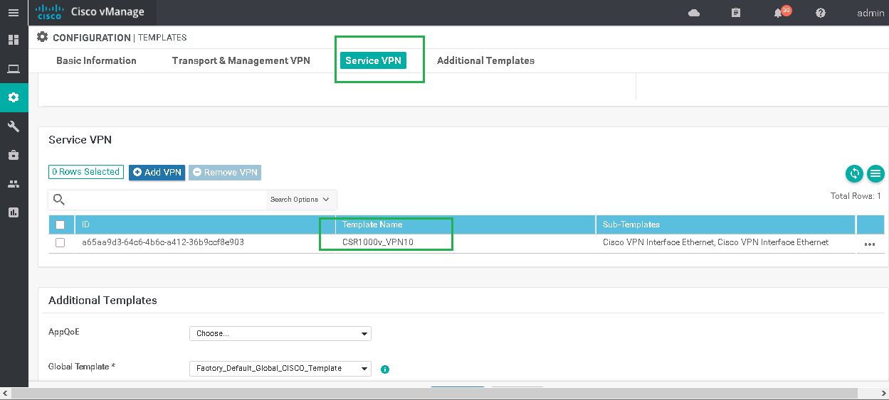
CONFIGURATION -> TEMPLATES -> CSR1000v_Device_Template -> CSR1000v_Device_Template -> Edit
Section: Service VPN
# Edit Feaure Template CSR1000v_VPN10
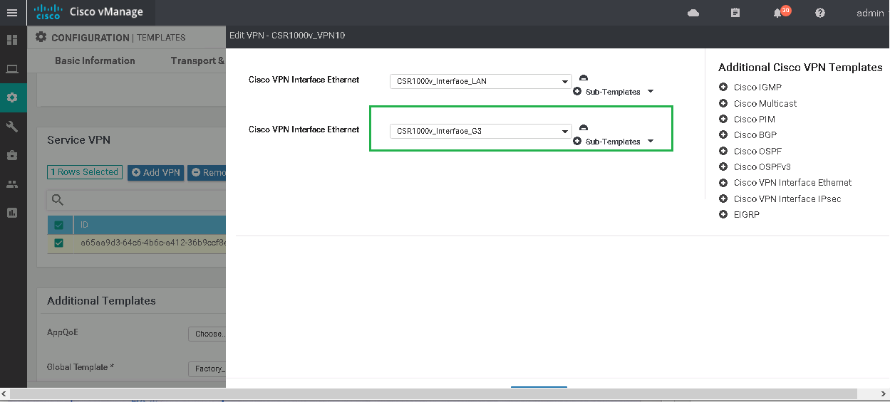
# Add Cisco VPN Interface Ethernet
Cisco VPN Interface Ethernet: CSR1000v_Interface_G3
then we have to configure IP address of GigabitEthernet3 for all branches.
# Edit Per device new Interface GigabitEthernet3 IP Configuration
 cEdge2: 172.16.12.1/24
 cEdge3: 172.16.13.1/24
 cEdge4: 172.16.14.1/24
Now we can check internet connectivity through router themselves and with the source of new GigabitEthernet3 interface .
cEdge4#ping vrf 10 8.8.8.8 source gigabitEthernet 3
Type escape sequence to abort.
Sending 5, 100-byte ICMP Echos to 8.8.8.8, timeout is 2 seconds:
Packet sent with a source address of 172.16.14.1
!!!!!
Success rate is 100 percent (5/5), round-trip min/avg/max = 56/80/146 ms
cEdge4#
for final test, we can check internet connectivity from a compute behind edge router in site4.
C:\Users\raykaremote>tracert -d 8.8.8.8

Tracing route to 8.8.8.8 over a maximum of 30 hops

  1    24 ms    <1 ms    <1 ms  172.16.14.1
  2     1 ms    <1 ms    <1 ms  192.168.2.101
  3     1 ms    <1 ms    <1 ms  172.16.11.2
  4     1 ms     1 ms     1 ms  192.168.1.1
.....C:\Users\raykaremote>ping 8.8.8.8
Pinging 8.8.8.8 with 32 bytes of data:
Reply from 8.8.8.8: bytes=32 time=64ms TTL=104
Reply from 8.8.8.8: bytes=32 time=51ms TTL=104
Reply from 8.8.8.8: bytes=32 time=52ms TTL=104
Reply from 8.8.8.8: bytes=32 time=53ms TTL=104
Ping statistics for 8.8.8.8:
Packets: Sent = 4, Received = 4, Lost = 0 (0% loss),
Approximate round trip times in milli-seconds:
Minimum = 51ms, Maximum = 64ms, Average = 55ms