OSPF in Service VPN in Cisco SD-WAN is the target of this section which means to enable OSPF routing protocol (and also static route) between WAN Edge router in main Office in our SD-WAN infrastructure and enterprise datacenter which is also located in the main office and then redistribute routes between OSPF and OMP Routing Protocol. Therefore, users all over SD-WAN Infrastructure can communicate with different areas of Enterprise such as data center.
SD-WAN Topology
First, let’s take a look at the topology to understand what we’re going to implement in this section. In this topology, it is assumed that enterprise data center is located at main office, which is site1 in our topology. our target is to enable users across SD-WAN infrastructure to communicate with data center services.
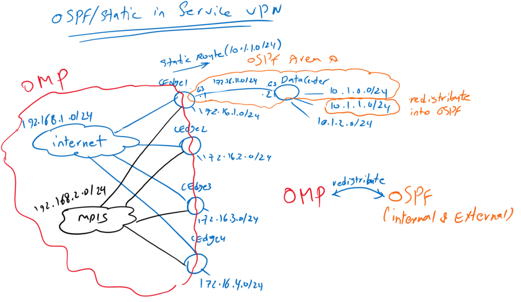
As you know, there is already an OMP routing protocol between WAN edge routers that allows users in the LAN section of all branches to communicate with each other. this is because connected routes in Service VPN, which are the LAN section of WAN edge routers, are automatically advertised through OMP routing protocol.
to enable users in all branches to communicate with data center in site1, we enable OSPF routing protocol between WAN edge router and data center in Site1. Data center routes are learned through OSPF routing protocol. then OSPF routes are redistributed in the OMP routing protocol. So all WAN routers in SD-WAN infrastructure learn the path to reach data center in site1.
Routes belonging to OMP routing protocol are also redistributed into OSPF, so routers in data center can learn how to reach users distributed in branches.
By default, connected routes, static routes, and internal OSPF routes are redistributed to OMP routing protocol. For testing purposes only, the subnet 10.1.1.0/24 in the data center will be advertised as an external OSPF route not normal OSPF route. Subnet 10.1.2.0/24 is also not advertised through OSPF, so a static route for this subnet is created in the WAN edge router in Site1. This is also just for testing purposes.
OSPF in Service VPN Configuration Procedure
To implement this scenario, we will go through this procedure.
- First, we will enable OSPF in data center router.
- Then a new Interface, GigabitEthernet3, for the connection between WAN edge router and data center will be configured in a new feature template
- We get a copy of VPN10 Service VPN template and add a static route for subnet 10.1.2.0/24. Another template is created because the static route only needs to be added in the WAN edge router in site1 and the configuration here is different with other WAN edge routers.
- A new template will be created to enable OSPF for the connection between WAN edge router1 and redistribute OMP routes into OSPF.
- A new template will be created for Cisco OMP protocol to redistribute OSPF internal and external routes and also Static route into OMP routing protocol.
- Finally a new Device Template for cEdge1 will be created because cEdge1 configuration is different from other edge routers. to do this, we will detach cEdge1 from current device template. a copy of current device template will be created. Then we will add new feature templates, interface GigabitEthernet3 and OSPF routing Protocol and also OMP configuration into new device template.
- Finally apply the new device template into cEdge1 router.
Step 1:
The first step is to enable OSPF in datacenter
GigabitEthernet3 is used to connect cEdge1 with Datacenter. Three loopback interface is created to simulate three subnet in datacenter. subnet 10.1.0.0/24 is advertised as internal OSPF route. subnet 10.1.1.0/24 is advertised as an external OSPF route just for testing purposes. subnet 10.1.2.0/24 is not advertised through OSPF again just for testing purposes.
!!! Data Center Router
interface GigabitEthernet3
 no shutdown
 ip address 172.16.11.2 255.255.255.0
!
interface loopback0
 no shutdown
 ip address 10.1.0.1 255.255.255.0
!
interface loopback1
 no shutdown
 ip address 10.1.1.1 255.255.255.0
!
interface loopback2
 no shutdown
 ip address 10.1.2.1 255.255.255.0
!
router ospf 1
 network 172.16.11.0 0.0.0.255 area 0
 network 10.1.0.0 0.0.0.255 area 0
 redistribute connected subnet route-map net_10_1_1
!
route-map net_10_1_1 permit 10
 match ip address prefix-list net_10_1_1
!
ip prefix-list net_10_1_1 permit 10.1.1.0/24 le 32
Step 2:
in the second step a new feature template will be created to add GigabitEthernet3 interface in cEdge1 for the connection with datacenter.
CONFIGURATION -> TEMPLATES -> Feature
device type: csr1000v
Template: Cisco VPN Interface Ethernet
Template Name: CSR1000v_Interface_Data_Center
Description: CSR1000v_Interface_Data_Center
Section: Basic Configuration
Step 3:
In Step 3, a copy of VPN10 Service VPN template is created to add a static route for subnet 10.1.2.0/24. Another template is created because static route is only needed to be added in cEdge1.
CONFIGURATION -> TEMPLATES -> Feature
device type: csr1000v
Template: Cisco VPN
Template Name: CSR1000v_VPN10_cEdge1
Description: CSR1000v_VPN10_cEdge1
Section: IPv4 Route
Step 4:
In Step 4, A new template will be created to enable OSPF for the connection between WAN edge router1 and redistribute OMP routes into OSPF
CONFIGURATION -> TEMPLATES -> Feature
device type: csr1000v
Template: Cisco OSPF
Template Name: CSR1000v_VPN10_OSPF
Description: CSR1000v_VPN10_OSPF
Section: Area
Section: Redistribute
Step 5:
In Step 5, A new template will be created for Cisco OMP protocol to redistribute OSPF internal and external routes and also Static route into OMP routing protocol.
CONFIGURATION -> TEMPLATES -> Feature
device type: csr1000v
Template: Cisco OMP
Template Name: CSR1000v_OMP
Description: CSR1000v_OMP
Section: Advertise
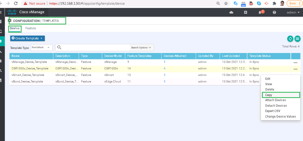
In Step 6, a new Device Template for cEdge1 will be created because cEdge1 configuration is different from other edge routers. to do this, we will detach cEdge1 from current device template. a copy of current device template will be created. Then we will add new feature templates, interface GigabitEthernet3 and OSPF routing Protocol and also OMP configuration into new device template.
CONFIGURATION -> TEMPLATES -> Device
!!! Detach cEdge1 from CSR1000v_Device_Template
!!! Copy CSR1000v_Device_Template to CSR1000v_Device_Template_cEdge1


Device Model: csr1000v
Template Name: CSR1000v_Device_Template_cEdge1
Description: CSR1000v_Device_Template_cEdge1
Section: Basic Information
Section: Service VPN
Remove old CSR1000v_VPN10 and replace it with new CSR1000v_VPN10_cEdge1 feature template.
In Final Step, attach cEdge1 to the new Template Template” CSR1000v_Device_Template_cEdge1″ , review and the apply the configuration.
just to make sure that datacenter routes are learned in SD-WAN infrastructure and SD-WAN infrastructure routes are learned in datacenter router, we will check routing table of cEdge2 and also datacemter.
cEdge2#show ip route vrf 10

Routing Table: 10
Codes: L - local, C - connected, S - static, R - RIP, M - mobile, B - BGP
       D - EIGRP, EX - EIGRP external, O - OSPF, IA - OSPF inter area
       N1 - OSPF NSSA external type 1, N2 - OSPF NSSA external type 2
       E1 - OSPF external type 1, E2 - OSPF external type 2, m - OMP
       n - NAT, Ni - NAT inside, No - NAT outside, Nd - NAT DIA
       i - IS-IS, su - IS-IS summary, L1 - IS-IS level-1, L2 - IS-IS level-2
       ia - IS-IS inter area, * - candidate default, U - per-user static route
       H - NHRP, G - NHRP registered, g - NHRP registration summary
       o - ODR, P - periodic downloaded static route, l - LISP
       a - application route
       + - replicated route, % - next hop override, p - overrides from PfR

Gateway of last resort is not set

      10.0.0.0/8 is variably subnetted, 3 subnets, 2 masks
m        10.1.0.1/32 [251/0] via 1.1.1.101, 00:00:26
m        10.1.1.0/24 [251/0] via 1.1.1.101, 00:00:26
m        10.1.2.0/24 [251/0] via 1.1.1.101, 00:00:31
      172.16.0.0/16 is variably subnetted, 6 subnets, 2 masks
m        172.16.1.0/24 [251/0] via 1.1.1.101, 1d04h
C        172.16.2.0/24 is directly connected, Loopback10
L        172.16.2.1/32 is directly connected, Loopback10
m        172.16.3.0/24 [251/0] via 1.1.1.103, 1d04h
m        172.16.4.0/24 [251/0] via 1.1.1.104, 1d04h
m        172.16.11.0/24 [251/0] via 1.1.1.101, 00:00:31
cEdge2#
as you can see, data center routes are learned in cEdge2 router.
Datacenter#show ip route
Codes: L - local, C - connected, S - static, R - RIP, M - mobile, B - BGP
       D - EIGRP, EX - EIGRP external, O - OSPF, IA - OSPF inter area
       N1 - OSPF NSSA external type 1, N2 - OSPF NSSA external type 2
       E1 - OSPF external type 1, E2 - OSPF external type 2, m - OMP
       n - NAT, Ni - NAT inside, No - NAT outside, Nd - NAT DIA
       i - IS-IS, su - IS-IS summary, L1 - IS-IS level-1, L2 - IS-IS level-2
       ia - IS-IS inter area, * - candidate default, U - per-user static route
       H - NHRP, G - NHRP registered, g - NHRP registration summary
       o - ODR, P - periodic downloaded static route, l - LISP
       a - application route
       + - replicated route, % - next hop override, p - overrides from PfR

Gateway of last resort is 192.168.1.1 to network 0.0.0.0

S*    0.0.0.0/0 [1/0] via 192.168.1.1
      10.0.0.0/8 is variably subnetted, 6 subnets, 2 masks
C        10.1.0.0/24 is directly connected, Loopback0
L        10.1.0.1/32 is directly connected, Loopback0
C        10.1.1.0/24 is directly connected, Loopback1
L        10.1.1.1/32 is directly connected, Loopback1
C        10.1.2.0/24 is directly connected, Loopback2
L        10.1.2.1/32 is directly connected, Loopback2
      172.16.0.0/16 is variably subnetted, 5 subnets, 2 masks
O E2     172.16.2.0/24
           [110/16777214] via 172.16.11.1, 04:50:02, GigabitEthernet3
O E2     172.16.3.0/24
           [110/16777214] via 172.16.11.1, 04:50:02, GigabitEthernet3
O E2     172.16.4.0/24
           [110/16777214] via 172.16.11.1, 04:50:02, GigabitEthernet3
C        172.16.11.0/24 is directly connected, GigabitEthernet3
L        172.16.11.2/32 is directly connected, GigabitEthernet3
      192.168.1.0/24 is variably subnetted, 2 subnets, 2 masks
C        192.168.1.0/24 is directly connected, GigabitEthernet1
L        192.168.1.2/32 is directly connected, GigabitEthernet1
      192.168.2.0/24 is variably subnetted, 2 subnets, 2 masks
C        192.168.2.0/24 is directly connected, GigabitEthernet2
L        192.168.2.1/32 is directly connected, GigabitEthernet2
Datacenter#
also SD-WAN infrastructure routes are learned in datacenter router.
with ping command, we can make sure of the connectivity between datacenter and SD-WAN infrastructure.
Datacenter#ping 172.16.2.1 source 10.1.2.1
Type escape sequence to abort.
Sending 5, 100-byte ICMP Echos to 172.16.2.1, timeout is 2 seconds:
Packet sent with a source address of 10.1.2.1
!!!!!
Success rate is 100 percent (5/5), round-trip min/avg/max = 1/1/2 ms
Datacenter#ping 172.16.3.1 source 10.1.1.1
Type escape sequence to abort.
Sending 5, 100-byte ICMP Echos to 172.16.3.1, timeout is 2 seconds:
Packet sent with a source address of 10.1.1.1
!!!!!
Success rate is 100 percent (5/5), round-trip min/avg/max = 1/1/2 ms
Datacenter#