Cisco SD-WAN QoS tools help us ensure the quality of applications. One of the most important tools is queuing, which prioritizes delay-sensitive applications and guarantees bandwidth for application in proportion to their needs, so that junk or bulk traffic does not occupy the entire bandwidth.
Cisco SD-WAN QoS: Topology Overview
This is the topology in which we have implemented Traffic Shaping in the last section.
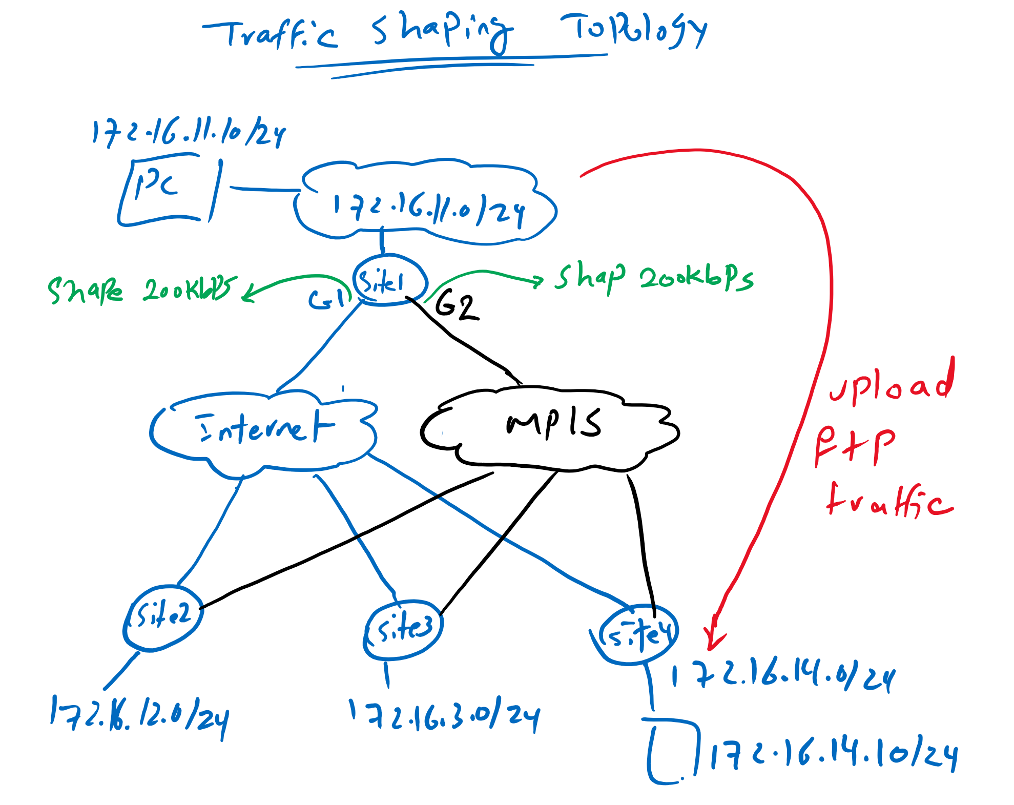
Just to review, four sites are connected through MPLS as well as Internet transport.
in both transport, bandwidth is limited to 200Kbps. Therefor we have shaped our traffic to 200kbps in the WAN edge routers so that when traffics are sent to ISP, extra traffics are queued in our WAN edge routers, instead of being dropped in the ISP.
Cisco SD-WAN QoS : Queuing Overview
Now we can manage queue created by shaping, in a way that traffic with different QoS requirements are inserted in different queue.
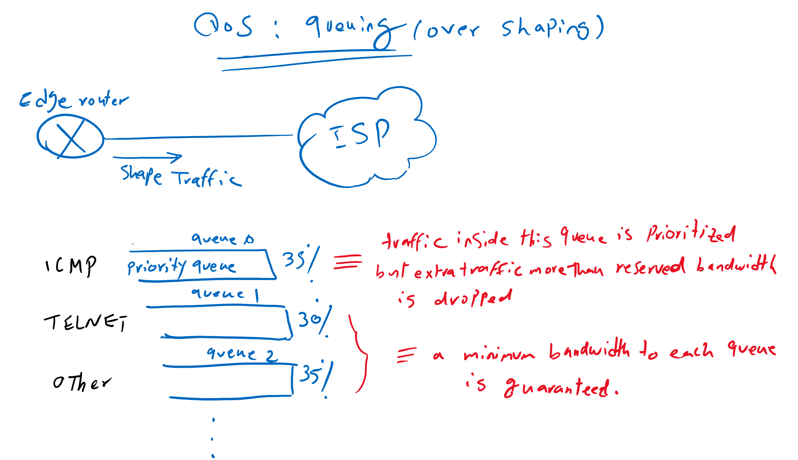
A queue is treated as a priority queue or a low latency queue (LLQ). All traffic in this queue is forwarded as quickly as possible, with the condition that it does not exceed a predefined bandwidth, otherwise other traffic cannot get bandwidth and they will get hungry. Because of this, extra traffic within the priority queue is discarded.
Every other queue is guaranteed a percentage of the bandwidth so we can ensure that every important application gets its own bandwidth it needs.
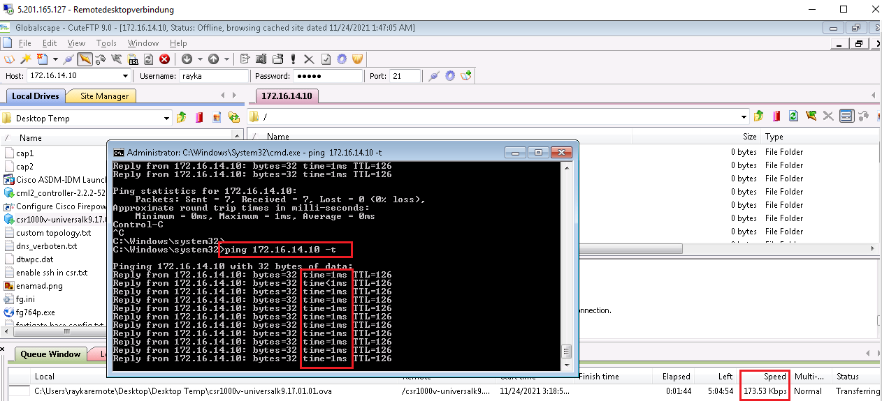
If you remember from previous section, without queuing, our ICMP and SSH traffic were disrupted when we try to upload a traffic through bulky ftp application.
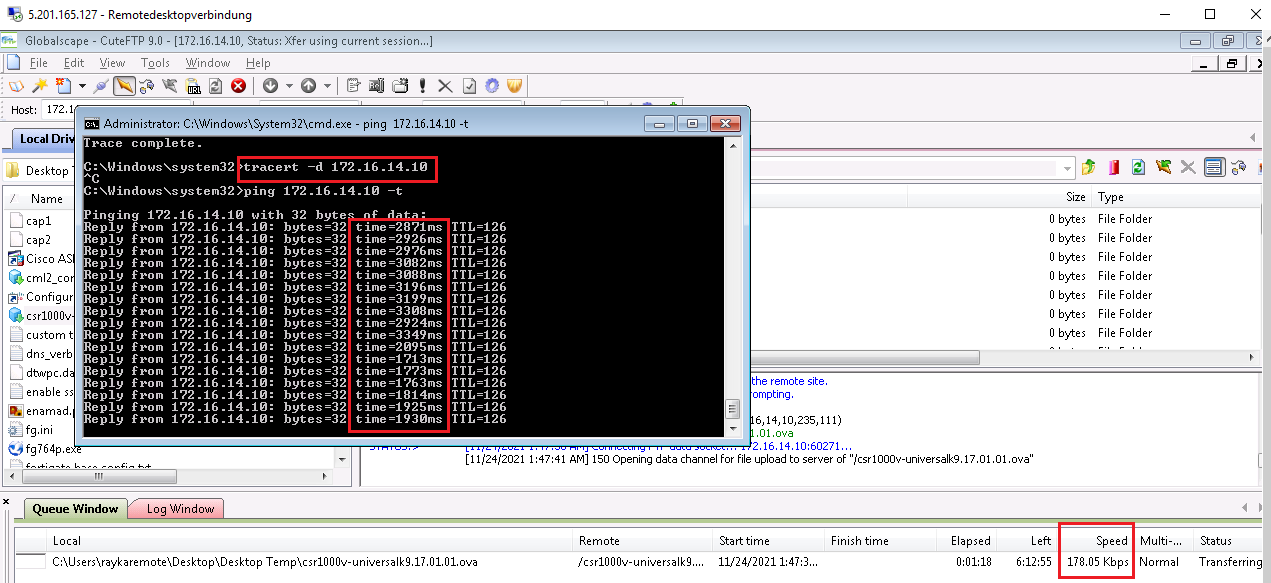
C:\Windows\system32>ping 172.16.14.10 -t

Pinging 172.16.14.10 with 32 bytes of data:
Reply from 172.16.14.10: bytes=32 time=2204ms TTL=126
Reply from 172.16.14.10: bytes=32 time=2257ms TTL=126
Reply from 172.16.14.10: bytes=32 time=2371ms TTL=126
Reply from 172.16.14.10: bytes=32 time=2367ms TTL=126
Reply from 172.16.14.10: bytes=32 time=2479ms TTL=126
Reply from 172.16.14.10: bytes=32 time=2473ms TTL=126

Ping statistics for 172.16.14.10:
    Packets: Sent = 6, Received = 6, Lost = 0 (0% loss),
Approximate round trip times in milli-seconds:
    Minimum = 2204ms, Maximum = 2479ms, Average = 2358ms
With queuing tool, we can prioritize or guarantee a minimum bandwidth to each application so that they are not disrupted when ftp application try to use entire bandwidth.
So we will put ICMP traffic inside LLQ or priority queue with a maximum bandwidth of 35%. SSH traffic inside queue 1 with minimum 30% bandwidth and all other traffic in queue 2 with minimum 35% bandwidth.
Cisco SD-WAN QoS: Queuing Configuration Steps
5 steps is required to implement this scenario:
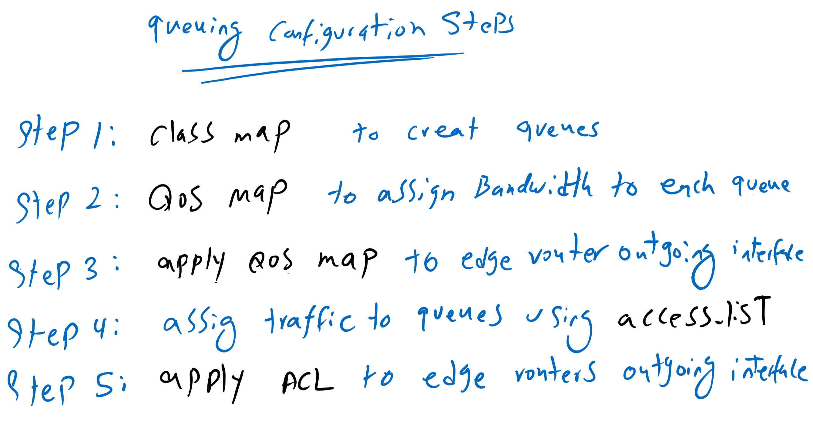
Step1: Class map: Create queues
In the first step, we create queues with the help of class map to create 3 queues. Queue 0 for ICMP traffic, Queue 1 for SSH Traffic and Queue 2 for other traffics including ftp.
Step2: QoS map: Assign a bandwidth to each queue
Queue 0 is priority queue by default. in step 2, we specify minimum bandwidth of every other queues. remaining bandwidth is the maximum bandwidth allowed by Queue 0 or LLQ
Step 3: Apply QoS Map to Edge routers outgoing interface
QoS Map must be finally applied to output interface
Step 4: Access List: Assign traffic related to each queue
In the next step we need to specify which traffic belongs to which queue. This is implemented using access list in cisco SD-WAN environment.
Step 5: Apply Access List to Edge routers outgoing interface
In the last step, the access list must be applied to edge router’s outgoing interface so that each traffic is served through its own queue.
Now we can start to implement queuing over shaping.
Step1: Class map: Create queues
In the first step, we create queues with the help of class map. With create 3 queues. Queue 0 for ICMP traffic, Queue 1 for SSH Traffic and Queue 2 for other traffics including ftp.
CONFIGURATION -> POLICIES -> Custom Options -> List -> Class Map -> New Class List
 Class: ICMP
 Queue: 0

 Class: SSH
 Queue: 1

 Class: BULK
 Queue: 2
Step2: QoS map: Assign a bandwidth to each queue
in step 2, we specify minimum bandwidth of every queues except queue 0. remaining bandwidth is the maximum bandwidth allowed by queue 0 or LLQ.
CONFIGURATION -> POLICIES -> Custom Options -> Forwarding Class/QoS -> QoS Map -> Add Qos Map -> create New -> Add Queue
 Name: QoS_Map1
 Description: QoS_Map1

  Queue: 0 #LLQ and do noot need to configure
  Bandwidth: 35%
  Buffer: 35%
  Drops: Tail

  Queue: 1
  Bandwidth: 30%
  Buffer: 30%
  Drops: Tail

  Queue: 2
  Bandwidth: 35%
  Buffer: 35%
  Drops: Tail
The new qos map must first be copied to edge routers before it is applied to the outgoing interface
# copy to edge1 router
CONFIGURATION -> POLICIES  -> Localized Policy -> cEdge1_Policy -> Forwarding Class/QoS -> QoS Map -> Add QoS Map -> Import Existing -> QoS_Map1

# copy to other edge routers
CONFIGURATION -> POLICIES  -> Localized Policy -> cEdge_Policy -> Forwarding Class/QoS -> QoS Map -> Add QoS Map -> Import Existing -> QoS_Map1
We can preview the configuration before they are copied to edge routers.
policy
  qos-scheduler QoS_Map1_0
   class Queue0
   bandwidth-percent 35
   buffer-percent 35
   scheduling llq
   drops tail-drop
   burst 15000
  !
  qos-scheduler QoS_Map1_1
   class Queue1
   bandwidth-percent 30
   buffer-percent 30
   scheduling wrr
   drops tail-drop
  !
  qos-scheduler QoS_Map1_2
   class Queue2
   bandwidth-percent 35
   buffer-percent 35
   scheduling wrr
   drops tail-drop
  !
  qos-map QoS_Map1
   qos-scheduler QoS_Map1_0
   qos-scheduler QoS_Map1_1
   qos-scheduler QoS_Map1_2
  !
  class-map
   class BULK queue 2
   class ICMP queue 0
   class Queue0 queue 0
   class Queue1 queue 1
   class Queue2 queue 2
   class SSH queue 1
  !
Step 3: Apply QoS Map to Edge routers outgoing interface
Now QoS Map must be applied to internet and mpls output interface.
CONFIGURATION -> TEMPLATES -> Feature -> CSR1000v_Interface_Internet -> Edit
 Section: ACL/QoS
  QoS Map: QoS_Map1

CONFIGURATION -> TEMPLATES -> Feature -> CSR1000v_Interface_MPLS -> Edit
 Section: ACL/QoS
  QoS Map: QoS_Map1
Let’s preview configuration changes.
policy-map shape_GigabitEthernet1
 class class-default
  service-policy QoS_Map1
  shape average 200000
As you can see, the shaping policy is already applied to the class default in Gigabitethernet1 interface. Now a new service policy is applied to the same class default that manages queues resulting from traffic shaping.
Step 4: Access List: Assign traffic related to each queue
In the next step we need to specify which traffic belongs to which queue. This is implemented using access list in cisco SD-WAN environment.
CONFIGURATION -> POLICIES  -> Custom Options -> Localized Policy -> Access Control Lists -> Add Access Control List polciy -> Add IPV4 ACL Policy
 Name: Traffic_to_Queue_ACL
 Description: Traffic_to_Queue_ACL

  Sequence 1:
   Match:
    Protocol: 1
   Action:
    Accept
    Class: ICMP

  Sequence 2:
   Match:
    Protocol: 6
    Destination Port: 22
   Action:
    Accept
    Class: SSH

  Sequence 3:
   Match:
    Protocol: 6
    Source Port: 22
   Action:
    Accept
    Class: SSH

  Sequence 4:
   Match:
    Protocol: 6
 source-ip: 172.16.11.10/32
 destination-ip: 172.16.14.10/32
   Action:
    Accept
    Class: BULK

  Sequence 5:
   Match:
    Protocol: 6
 source-ip: 172.16.14.10/32
 destination-ip: 172.16.11.10/32
   Action:
    Accept
    Class: BULK

  Default Action: Accept
The new access-list must first be copied to edge routers before it is applied to the outgoing interface
# copy to cEdge1 touter
CONFIGURATION -> POLICIES  -> Localized Policy -> cEdge1_Policy -> Access Control List -> Add Access Control List Policy -> Import Existing -> Traffic_to_Queue_ACL

# copy to other edge routers
CONFIGURATION -> POLICIES  -> Localized Policy -> cEdge_Policy -> Access Control List -> Add Access Control List Policy -> Import Existing -> Traffic_to_Queue_ACL
Now we can preview the configuration before it is copied to edge routers.
policy
 access-list Traffic_to_Queue_ACL
  sequence 1
   match
    protocol 1
   !
   action accept
    class ICMP
   !
  !
  sequence 11
   match
    destination-port 22
    protocol         6
   !
   action accept
    class SSH
   !
  !
  sequence 21
   match
    source-port 22
    protocol    6
   !
   action accept
    class SSH
   !
  !
  sequence 31
   match
    source-ip      172.16.11.10/32
    destination-ip 172.16.14.10/32
    protocol       6
   !
   action accept
    class BULK
   !
  !
  sequence 41
   match
    source-ip      172.16.14.10/32
    destination-ip 172.16.11.10/32
    protocol       6
   !
   action accept
    class BULK
   !
  !
  default-action accept
Step 5: Apply Access List to Edge routers outgoing interface
In the last step, the access list must be applied to edge router’s outgoing interface so that each traffic is served through its own queue.
CONFIGURATION -> TEMPLATES -> Feature -> CSR1000v_Interface_Internet -> Edit
 Section: ACL/QoS
  Egress ACL - IPv4: On
  IPv4 Egress Access List: Traffic_to_Queue_ACL
We can preview the configuration changes.
sdwan
 interface GigabitEthernet1
  access-list Traffic_to_Queue_ACL out
It shows that access list will be applied to interface Gigabitethernet1.
Cisco SD-WAn QoS : Queuing Monitoring
Now we can upload ftp traffic again and at the same send ping traffic.
It is expected that there is no problem with ICMP and SSH traffic any more since they have their own bandwidth reserved through queuing mechanism.
We can also check the result of our policy with command “show policy-map interface Gigabitethernet 1”.
cEdge1#show policy-map interface gigabitEthernet 1
 GigabitEthernet1

  Service-policy output: shape_GigabitEthernet1

    Class-map: class-default (match-any)
      1680712 packets, 416671989 bytes
      30 second offered rate 23000 bps, drop rate 0000 bps
      Match: any
      Queueing
      queue limit 64 packets
      (queue depth/total drops/no-buffer drops) 0/798/0
      (pkts output/bytes output) 230991/157236275
      shape (average) cir 200000, bc 800, be 800
      target shape rate 200000

      Service-policy : QoS_Map1

        queue stats for all priority classes:
          Queueing
          priority level 1
          queue limit 512 packets
          (queue depth/total drops/no-buffer drops) 0/0/0
          (pkts output/bytes output) 3575/616852

        Class-map: Queue0 (match-any)
          3575 packets, 616852 bytes
          30 second offered rate 21000 bps, drop rate 0000 bps
          Match: qos-group 0
          Priority: Strict, b/w exceed drops: 0

          Priority Level: 1
          police:
              rate 35 %
              rate 70000 bps, burst 2187 bytes
            conformed 3575 packets, 616852 bytes; actions:
              transmit
            exceeded 0 packets, 0 bytes; actions:
              drop
            conformed 21000 bps, exceeded 0000 bps

        Class-map: Queue1 (match-any)
          0 packets, 0 bytes
          30 second offered rate 0000 bps, drop rate 0000 bps
          Match: qos-group 1
          Queueing
          queue limit 64 packets
          (queue depth/total drops/no-buffer drops) 0/0/0
          (pkts output/bytes output) 0/0
          bandwidth remaining ratio 30

        Class-map: class-default (match-any)
          402 packets, 51889 bytes
          30 second offered rate 2000 bps, drop rate 0000 bps
          Match: any
          Queueing
          queue limit 64 packets
          (queue depth/total drops/no-buffer drops) 0/0/0
          (pkts output/bytes output) 402/51889
          bandwidth remaining ratio 35
cEdge1#
As you can see, entire interface bandwidth is shaped to 200kbps. offer rate and drop rate of the last 30 seconds is also displayed.
It also shows that QoS_Map1 is applied to the queue resulting from shaping.
For each queue and also class default, offer rate and drop rate is shown. The number of packet in queue and the number of dropped packets are also displayed.
Queue 0 is for our ICMP traffic. this is the only queue that the rate of traffic is limited since traffic inside this queue is forwarded with high priority.
Queue 1 is for our SSH traffic. there is no packet matched with queue1 which is actually not as my expectation.
There is no Queue2 at all to match ftp traffic.
I am not sure if there is a mistake in my configuration or it is a bug with cisco SD-WAN software.