Cisco SD-WAN Traffic Shaping is another QoS feature for limiting traffic bandwidth. What is the difference between traffic policing and traffic shaping? Where traffic shaping or traffic policing is used? These are the questions which will be answered in this section.
Traffic Shaping versus Traffic Policing
If we want to have a definition of traffic policing and traffic shaping, both are used to limit bandwidth.
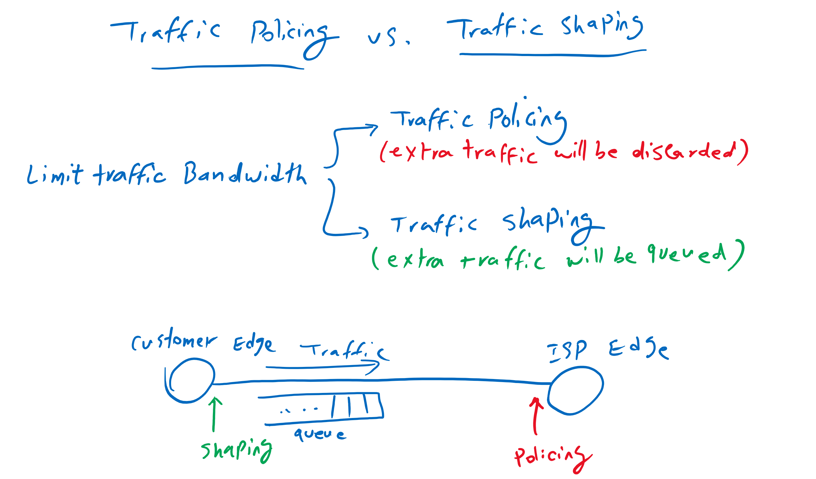
Traffic policing discards extra traffic that violates the bandwidth policy. However, with traffic shaping, extra traffic is queued and forwarded with a delay when there is less traffic.
Traffic policing is usually used at ISP to limit customer’s traffic according to their purchased bandwidth and of course extra traffic will be discarded. However, traffic shaping is typically used on customer side to limit traffic bandwidth and queue extra traffic before they are sent to the ISP. therefore, important traffic will be delayed on our site, which is better than being discarded on IPS site.
Traffic Shaping Topology
This is the topology in which we will implement traffic shaping. Site1 through Site4 are connected to each other through two transports, Internet and MPLS.
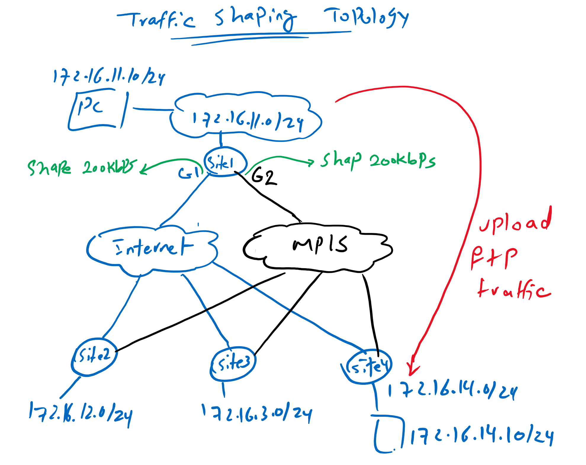
Usually the bandwidth of our transports are limited and our extra traffic is dropped by the ISP. It therefore makes sense to shape our traffic in WAN edge routers according to the purchased bandwidth so that extra traffic is queued and delayed instead of being discarded at the ISP.
Another point to mention is that with traffic shaping and policing we can limit the bandwidth of a specific traffic or bandwidth of an interface as a whole. What we are going to implement in this section is to limit the bandwidth of the transport interfaces as a whole.
Just to check the bandwidth, I am using two computers in Site1 and Site4 with IP addresses 172.16.11.10 and 172.16.14.10. I will shape the bandwidth of MPLS and internet to 200kbps. Then I will try to upload FTP traffic from Site1 to Site4.
Cisco SD-WAN Traffic Shaping Configuration
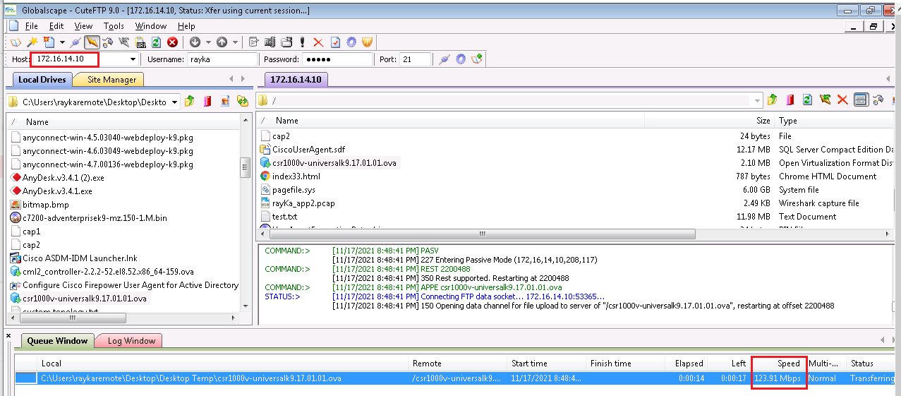
Before we start configuring bandwidth shaping, let’s check how much bandwidth we have from Site1 to Site4 if there is no restriction. We check it with sending ftp traffic from site1 to site4.
I stop FTP connection and ping from Site1 to Site4. So in the next step we can check if it is being affected by traffic shaping and FTP traffic.
Now we can start configuring traffic shaping. It is very easy to limit the bandwidth of transport interfaces with traffic shaping. It is a part of the transport interface feature template that we have already implemented.
It must be done for both transport interface.
CONFIGURATION -> TEMPLATES -> Feature -> CSR1000v_Interface_Internet -> Edit
 Section: ACL/QoS
 Shaping Rate (Kbps) : 200
!
CONFIGURATION -> TEMPLATES -> Feature -> CSR1000v_Interface_MPLS -> Edit
 Section: ACL/QoS
 Shaping Rate (Kbps) : 200
We can also preview configuration changes. As you can see, a new policy map is being created. inside policy map and inside class default, which includes all data traffic, traffic is shaped to 200 kbps.
# Internet Transport
policy-map shape_GigabitEthernet1
 class class-default
  shape average 200000
 !
!
interface GigabitEthernet1
 service-policy output shape_GigabitEthernet1
!
# MPLS Transport
policy-map shape_GigabitEthernet2
 class class-default
  shape average 200000
 !
!
interface GigabitEthernet2
 service-policy output shape_GigabitEthernet2
Cisco SD-WAN Traffic Shaing Monitoring
After applying the shaping policy to both transport interfaces, we will re-upload FTP traffic from Site1 to Site4 to see if it is really shaped.
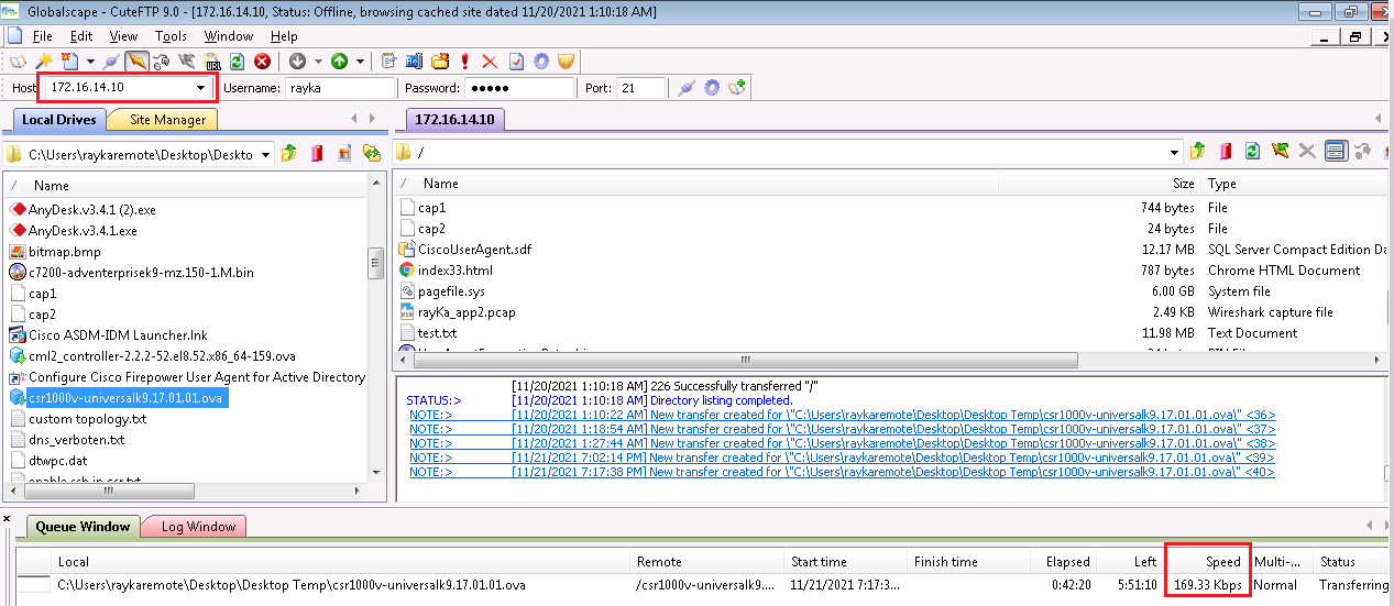
As you can see the bandwidth is now limited to about 200kbps.
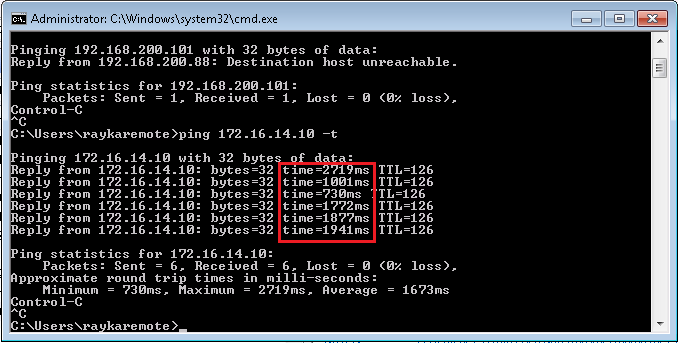
The ping traffic now has a large delay and is affected by FTP traffic.
My Telnet connection is also very slow because of traffic shaping and also FTP traffic that is using all of the bandwidth.
The discussion of next section is to guarantee the bandwidth of important traffics and give priority to delay sensitive traffic to ensure that they are not impacted with bulk and junk traffic.
Now let’s also check it with CLI command to make sure the traffic is matched with our policy and also other details that may be shown in CLI environment.
In the output of “show policy-map interface GigabitEthernet 1” command we can see the rate of sending traffic, the rate of the drop when the queue is full, the length of the queue, current number of packets inside queue and the number of dropped packets when the queue is full.
cEdge1#show policy-map interface gigabitEthernet 1
 GigabitEthernet1

  Service-policy output: shape_GigabitEthernet1

    Class-map: class-default (match-any)
      106423 packets, 78062321 bytes
      30 second offered rate 224000 bps, drop rate 0000 bps
      Match: any
      Queueing
      queue limit 64 packets
      (queue depth/total drops/no-buffer drops) 54/447/0
      (pkts output/bytes output) 58225/69262420
      shape (average) cir 200000, bc 800, be 800
      target shape rate 200000
cEdge1#
In the next section we will manage the queue created by traffic shaping to prioritize and guarantee bandwidth.