Cisco SD-WAN Direct Internet Access enables sites to use the same Internet that is used for SD-WAN inter-site and internal transport connectivity. direct internet access and service publishing are implemented using NAT technology. These are the concepts that we will implement in this section.
Cisco SD-WAN Indirect Internet Access review
In the previous sections, we enabled branch offices to use the Internet service VPN in central office through an IPsec tunnel with this site. The most important point in this solution is to advertise the default route to other branches at the central office and in Service VPN that internet connectivity is provided.
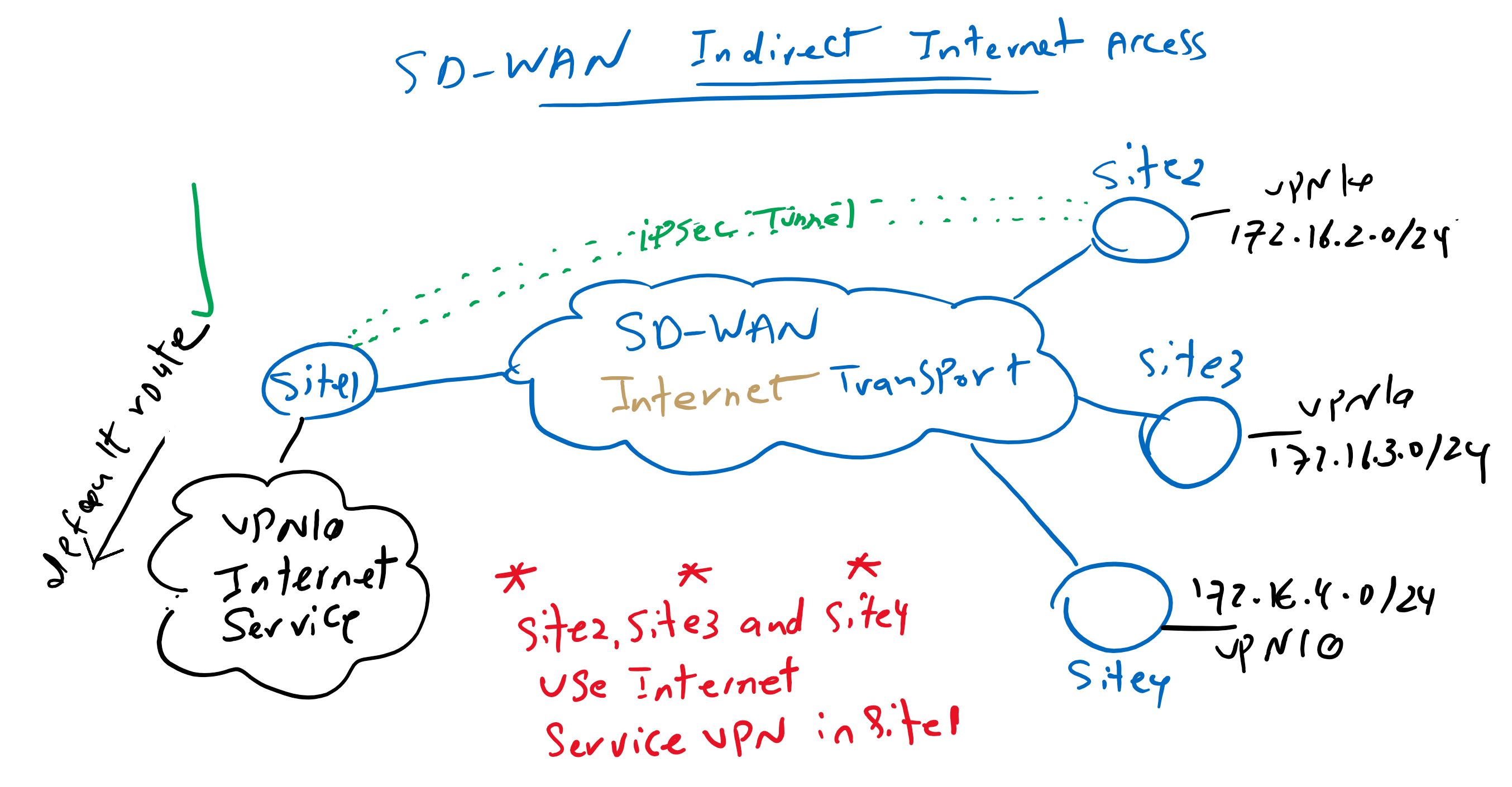
In this topology, that we have implemented in previous sections, we have internet connectivity in Site1 and in Service VPN 10 (VRF 10). We advertise default route from Site1 to other sites through OMP routing protocol.
Therefore other site’s default route point to site1 Service VPN 10. The internet traffic from branches is forwarded through IPsec Tunnel to siet1 and then it is forwarded into internet which can be different from internet connectivity which is used as SD-WAN transport.
Cisco SD-WAN Direct Internet Access Overview
However, traffic related to direct internet access is not forwarded through IPsec tunnel to a central site, but it is forwarded directly over SD-WAN internet transport using NAT technology.
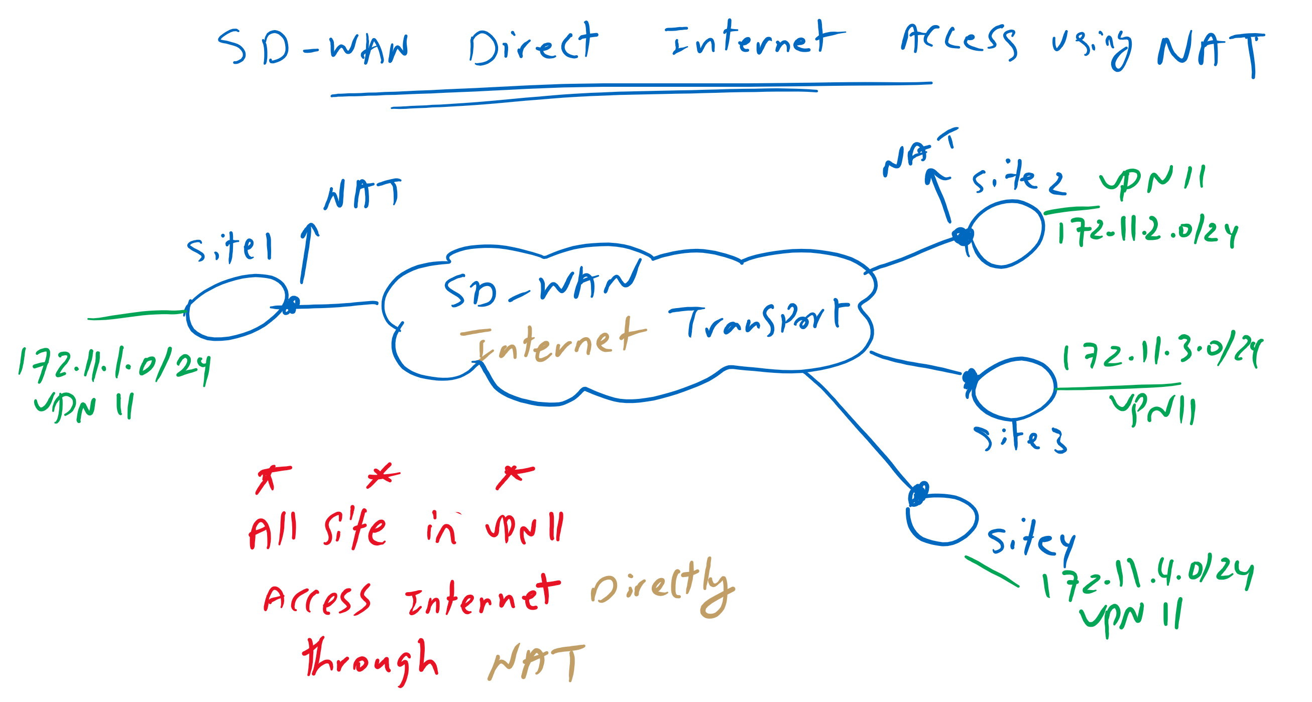
As it is shown in the topology, NAT is implemented in WAN edge routers and in every site that we need direct internet connectivity. It uses the same internet connectivity which is used in SD-WAN infrastructure to transport inter-sites internal traffics.
Cisco SD-WAN NAT Types
In this method, NAT is implemented in WAN edge routers and supports various types of NAT technology, not only to allow users behind WAN edge routers to access the Internet (source NAT), but also to publish services behind WAN edge routers over the Internet (destination NAT).
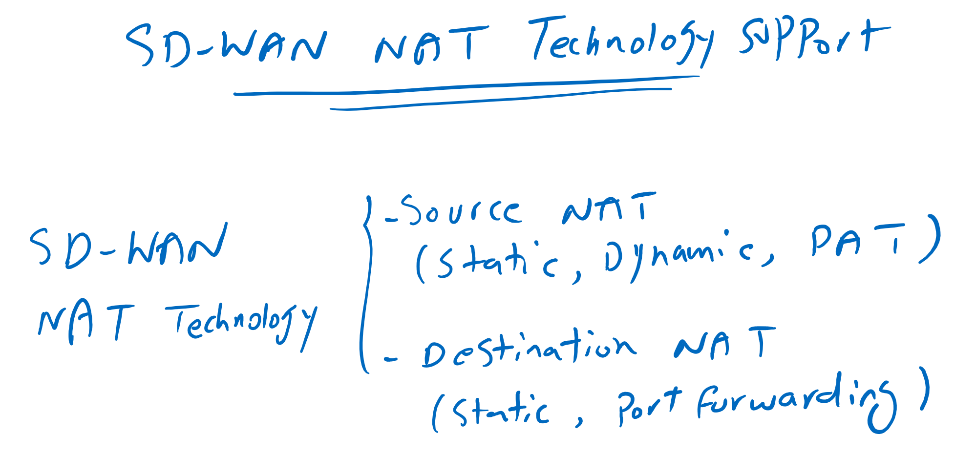
In other words, it supports source NAT with options Static NAT, Dynamic NAT and also PAT, the most common option in Source NAT.
It also supports destination NAT to publish services. not only with Static NAT which reserve an IP address for each service, but also supports pot forwarding which use one IP address to publish many services with different ports.
I will not discuss about NAT technology and it is assumed that you know details of this technology.
default route per VPN in SD-WAN direct inetrnet access
I would like to add two more points in Cisco SD-WAN Direct Internet Access concept. First point is that Internet access can be activated per VPN service. In every VPN service that you want to give
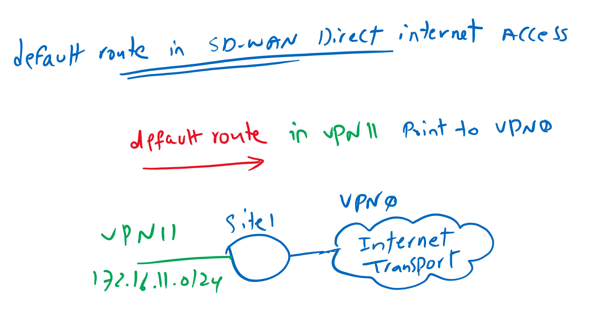
direct internet access, you need to advertise a default route. In our topology I activate direct internet access for VPN 11.
Another point is that the next-hop IP address of the default route is in a different VPN (or VRF). In our topology we will add the default route in VPN 11 but the next hop address is in VPN0 which is Transport VRF.
This is not a normal static route and it is usually used when we want to share an internet in different VRFs. In our topology, internet connectivity in VRF 0 can be shared for both VPN 10 and VPN 11
Cisco SD-WAN direct Internet Access configuration
Now we can start to implement direct internet access and also service publishing without discussing NAT technology itself.
For enabling direct internet access, we need to enable source NAT in internet transport connected to WAN edge routers and also add a default route in VPN 11 which is going to have direct internet access.
Before staring let’s check internet connectivity in cEdge1 in VPN 11 to make sure that it has no internet connectivity.
cEdge1#ping vrf 11 8.8.8.8
Type escape sequence to abort.
Sending 5, 100-byte ICMP Echos to 8.8.8.8, timeout is 2 seconds:
.....
Success rate is 0 percent (0/5)
We enable source NAT in Transport Internet through feature template dedicated for internet transport “CSR1000v_Interface_Internet”. As you can see in the picture, we have three options for NAT implementation, static NAT, dynamic NAT with pool and PAT with outgoing interface or loopback interface. We will only implement the PAT option as they are not complex to implement.

CONFIGURATION -> TEMPLATES -> Feature -> CSR1000v_Interface_Internet -> Edit
 Section: NAT
  NAT: On
  NAT Type: Interface
we can preview configuration changes, as you can see, it is a normal PAT rule.
ip nat inside source list nat-dia-vpn-hop-access-list interface GigabitEthernet1 overload

interface GigabitEthernet1
 ip nat outside
Then we have to advertise the default route in VPN 11, which points to internet transport in VPN 0. In vManage GUI, it is a little strange to implement this type of default route. We have to select the VPN option as the gateway address.
CONFIGURATION -> TEMPLATES -> Feature -> CSR1000v_VPN11 -> Edit
 Section: IPv4 ROUTE -> New IPv4 Route
  Prefix: 0.0.0.0/0
  Gateway: VPN
  Enable VPN: On
But when we preview the configuration changes it seems normal as the default route is in VPN 11 but the next hop address is added as a global option which means it is in global VRF or VRF 0.
ip nat route vrf 11 0.0.0.0 0.0.0.0 globalThese two steps are enough to have internet connectivity. Let’s check again internet connectivity in cEdge1 in VPN 11.
cEdge1#ping vrf 11 8.8.8.8
Type escape sequence to abort.
Sending 5, 100-byte ICMP Echos to 8.8.8.8, timeout is 2 seconds:
!!!!!
Success rate is 100 percent (5/5), round-trip min/avg/max = 52/63/86 ms

cEdge1#ping vrf 11 4.2.2.4
Type escape sequence to abort.
Sending 5, 100-byte ICMP Echos to 4.2.2.4, timeout is 2 seconds:
!!!!!
Success rate is 100 percent (5/5), round-trip min/avg/max = 121/127/131 ms
With “show ip nat translations” command, we can make sure that traffic are passing through NAT rule.
cEdge1#show ip nat translations
Pro  Inside global         Inside local          Outside local         Outside global
icmp 192.168.1.101:21      172.11.1.1:21         8.8.8.8:21            8.8.8.8:21
icmp 192.168.1.101:22      172.11.1.1:22         4.2.2.4:22            4.2.2.4:22
Total number of translations: 2
we can also check vrf 11 routing table to check the default route.
cEdge1#show ip route vrf 11

Routing Table: 11
Codes: L - local, C - connected, S - static, R - RIP, M - mobile, B - BGP
       D - EIGRP, EX - EIGRP external, O - OSPF, IA - OSPF inter area
       N1 - OSPF NSSA external type 1, N2 - OSPF NSSA external type 2
       E1 - OSPF external type 1, E2 - OSPF external type 2, m - OMP
       n - NAT, Ni - NAT inside, No - NAT outside, Nd - NAT DIA
       i - IS-IS, su - IS-IS summary, L1 - IS-IS level-1, L2 - IS-IS level-2
       ia - IS-IS inter area, * - candidate default, U - per-user static route
       H - NHRP, G - NHRP registered, g - NHRP registration summary
       o - ODR, P - periodic downloaded static route, l - LISP
       a - application route
       + - replicated route, % - next hop override, p - overrides from PfR

Gateway of last resort is 0.0.0.0 to network 0.0.0.0

n*Nd  0.0.0.0/0 [6/0], 00:07:22, Null0
      10.0.0.0/8 is variably subnetted, 3 subnets, 2 masks
m        10.1.0.1/32 [251/0] via 1.1.1.101 (10), 00:45:17
m        10.1.1.0/24 [251/0] via 1.1.1.101 (10), 00:45:17
m        10.1.2.0/24 [251/0] via 1.1.1.101 (10), 00:45:17
      172.11.0.0/16 is variably subnetted, 5 subnets, 2 masks
C        172.11.1.0/24 is directly connected, Loopback11
L        172.11.1.1/32 is directly connected, Loopback11
m        172.11.2.0/24 [251/0] via 1.1.1.102, 00:45:17
m        172.11.3.0/24 [251/0] via 1.1.1.103, 00:45:02
m        172.11.4.0/24 [251/0] via 1.1.1.104, 00:45:01
      172.16.0.0/24 is subnetted, 8 subnets
m        172.16.1.0 [251/0] via 1.1.1.101 (10), 00:45:17
m        172.16.2.0 [251/0] via 1.1.1.102, 00:45:17
m        172.16.3.0 [251/0] via 1.1.1.103, 00:45:02
m        172.16.4.0 [251/0] via 1.1.1.104, 00:45:01
m        172.16.11.0 [251/0] via 1.1.1.101 (10), 00:45:17
m        172.16.12.0 [251/0] via 1.1.1.102, 00:45:17
m        172.16.13.0 [251/0] via 1.1.1.103, 00:45:02
m        172.16.14.0 [251/0] via 1.1.1.104, 00:45:01
as you can see, beside default route, flags “n*Nd” exist. “n” means NAT. “*” means default gateway. “Nd” means “NAT DIA” or Direct Internet Access.
Cisco SD-WAN NAT configuration for Service Publishing
we are also able to publish services through implementing destination static NAT and port forwarding in WAN edge routers.
in this section, we implement static NAT in cEdge1 router in Site1.
Adding static route, must be configured through internet transport feature template.
Since this template is shared between all WAN edge routers and we are going to configure destination NAT just in cEdge1 router. We take a copy from this template and assign it to cEdge1 router so destination NAT can be edited in cEdge1 router independent of other WAN edge routers.
CONFIGURATION -> TEMPLATES -> Feature -> CSR1000v_Interface_Internet -> copy
 Name: CSR1000v_Interface_Internet_cEdge1
 Description: CSR1000v_Interface_Internet_cEdge1

CONFIGURATION -> TEMPLATES -> Device -> CSR1000v_Device_Template_cEdge1 -> Edit
 Cisco VPN Interface Ethernet: change from CSR1000v_Interface_Internet to CSR1000v_Interface_Internet_cEdge1
Now we can add a new static NAT rule to publish a service through internet. My internal interface is a loopback interface. So I will configure destination NAT but there is no services behind this interface to test the result of the configuration.
CONFIGURATION -> TEMPLATES -> Feature -> CSR1000v_Interface_Internet_cEdge1 -> Edit
 Section: NAT -> New Static NAT
  Source IP Address: 172.11.1.1
  Translated Source IP Address: 192.168.1.211
We can preview the configuration changes. It must be a normal static nat rule.
ip nat inside source static 172.11.1.1 192.168.1.211 egress-interface GigabitEthernet1