Cisco ISIS IPv6 configuration example in a single topology is the topic of this section.
Single topology means we assume we have common and equal IPv4 and IPv6 topology.
Multiple topology, in which IPv4 and IPv6 can have a different topology, will be discussed in the next section.
Cisco ISIS IPv6 Fundamental
The ISIS protocol is an extensible protocol and can advertise different types of addresses such as IPv4 and IPv6.
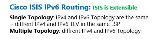
This is because ISIS protocol is based on TLVs. That means, to advertise a new address field, it is enough to add a new TLV specifying the type, length and value of the new field and there is no need to completely change the format of the packet.
For this reason, the ISIS protocol is one of the few protocols that did not need to be rewritten to advertise IPV6, but only a new TLV was added to this protocol that provides the ability to advertise IPV6 addresses.
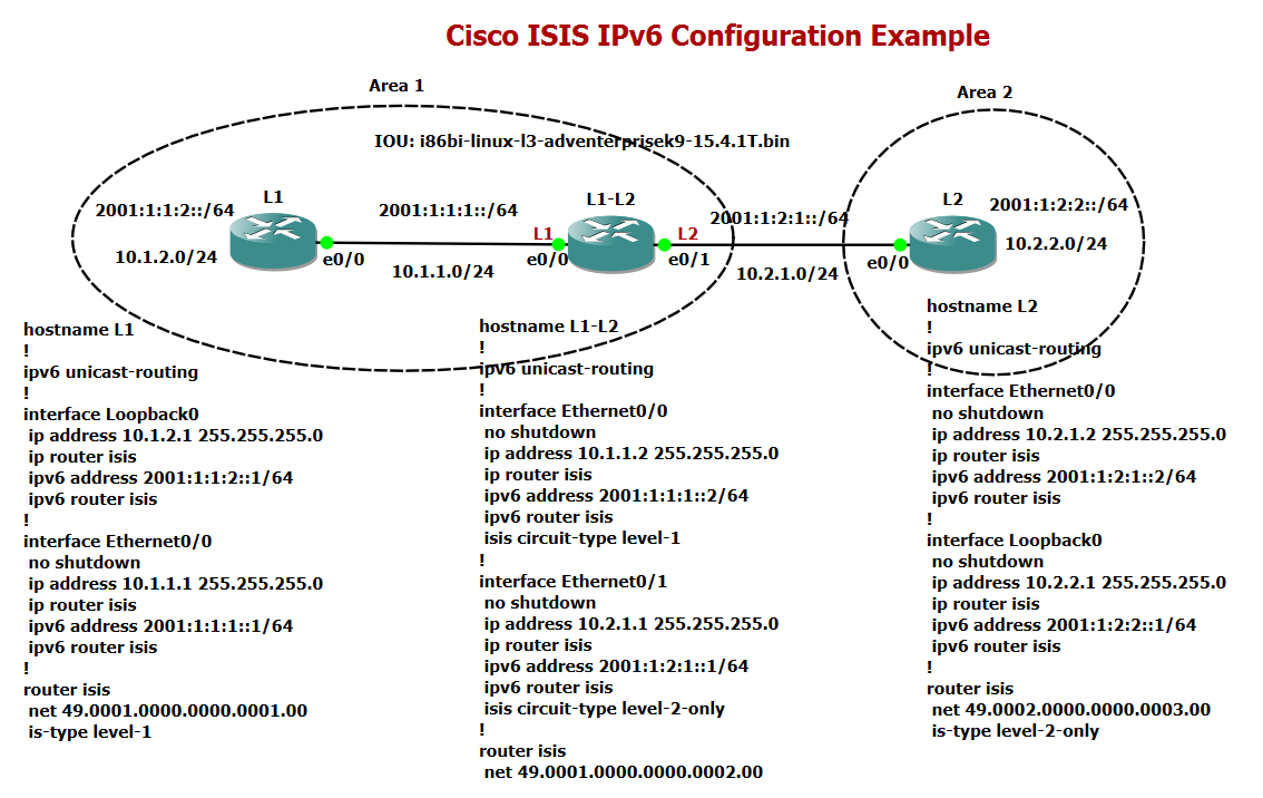
Cisco ISIS IPv6 Configuration Example
In this topology, where both IPv4 and IPv6 are addressed, we want to show how IPv6 is configured alongside IPv4 in ISIS.
This is a single topology configuration example since wherever IPv4 address is configured, we also have an IPv6 address.
In a single topology configuration example, we enable isis for IPv4 with “ip router isis” under interface and at the same time we enable isis for IPv6 with “ipv6 router isis” command.
The other confgurations are the same as previous examples. the type of IS is configured level 1 in router L1 and level 2 in router L2. the type of IS in router L1-L2 is both level 1 and level 2 by default. but we configure the interface connected to L2 router as level 2 and interface connected to router L1 as level 1.
!!! L1
hostname L1
!
ipv6 unicast-routing
!
interface Loopback0
 ip address 10.1.2.1 255.255.255.0
 ip router isis
 ipv6 address 2001:1:1:2::1/64
 ipv6 router isis
!
interface Ethernet0/0
 no shutdown
 ip address 10.1.1.1 255.255.255.0
 ip router isis
 ipv6 address 2001:1:1:1::1/64
 ipv6 router isis
!
!
router isis
 net 49.0001.0000.0000.0001.00
 is-type level-1


!!! L1-L2
hostname L1-L2
!
ipv6 unicast-routing
!
interface Ethernet0/0
 no shutdown
 ip address 10.1.1.2 255.255.255.0
 ip router isis
 ipv6 address 2001:1:1:1::2/64
 ipv6 router isis
 isis circuit-type level-1
!
interface Ethernet0/1
 no shutdown
 ip address 10.2.1.1 255.255.255.0
 ip router isis
 ipv6 address 2001:1:2:1::1/64
 ipv6 router isis
 isis circuit-type level-2-only
!
!
router isis
 net 49.0001.0000.0000.0002.00


!!! L2
hostname L2
!
ipv6 unicast-routing
!
interface Ethernet0/0
 no shutdown
 ip address 10.2.1.2 255.255.255.0
 ip router isis
 ipv6 address 2001:1:2:1::2/64
 ipv6 router isis
!
interface Loopback0
 no shutdown
 ip address 10.2.2.1 255.255.255.0
 ip router isis
 ipv6 address 2001:1:2:2::1/64
 ipv6 router isis
!
!
router isis
 net 49.0002.0000.0000.0003.00
 is-type level-2-only
As you can see, implementing ISIS on IPv4 and IPv6 protocols does not require configuring and running two independent ISIS processes. Rather, ISIS is able to advertise both types of addresses in just one LSP, but with two different types of TLVs.
To implement some features of ISIS, such as summarization in both IPv4 and IPv6, the “address family” will be used to separate the configuration of IPv4 and IPv6.
L2(config)#router isis
L2(config-router)#address-family ?
  ipv4  Address family
  ipv6  Address family
The output of the L2-router database table contains three LSPs, each sent from one of the routers in the topology.
L2#show isis database

IS-IS Level-2 Link State Database:
LSPID                 LSP Seq Num  LSP Checksum  LSP Holdtime      ATT/P/OL
L1-L2.00-00           0x0000000D   0x312D        1090              0/0/0
L2.00-00            * 0x00000006   0x436B        826               0/0/0
L2.01-00            * 0x00000004   0x27AC        826               0/0/0
If we look at the database details output and at the NLPID field, you can see that two TLVs numbered 0xCC and 0x8E were sent from two routers L1-L2 and L2, one of which is related to IPV4 addresses and the other related to IPv6 addresses. What is noticeable here is that both addresses are sent in the same LSP.
L2#show isis database detail

IS-IS Level-2 Link State Database:
LSPID                 LSP Seq Num  LSP Checksum  LSP Holdtime      ATT/P/OL
L1-L2.00-00           0x0000000D   0x312D        1055              0/0/0
  Area Address: 49.0001
  NLPID:        0xCC 0x8E
  Hostname: L1-L2
  IP Address:   10.2.1.1
  Metric: 10         IP 10.2.1.0 255.255.255.0
  IPv6 Address: 2001:1:2:1::1
  Metric: 10         IPv6 2001:1:2:1::/64
  Metric: 10         IS L2.01
  Metric: 10         IP 10.1.1.0 255.255.255.0
  Metric: 20         IP 10.1.2.0 255.255.255.0
  Metric: 10         IPv6 2001:1:1:1::/64
  Metric: 20         IPv6 2001:1:1:2::/64
L2.00-00            * 0x00000006   0x436B        791               0/0/0
  Area Address: 49.0002
  NLPID:        0xCC 0x8E
  Hostname: L2
  IP Address:   10.2.2.1
  IPv6 Address: 2001:1:2:2::1
  Metric: 10         IS L2.01
  Metric: 10         IP 10.2.1.0 255.255.255.0
  Metric: 10         IP 10.2.2.0 255.255.255.0
  Metric: 10         IPv6 2001:1:2:1::/64
  Metric: 10         IPv6 2001:1:2:2::/64
L2.01-00            * 0x00000004   0x27AC        791               0/0/0
  Metric: 0          IS L2.00
  Metric: 0          IS L1-L2.00