ISIS route leaking gives the capability to redistribute level 2 routes into level 1 domain. It can help to prevent sub-optimal routing when there is more than one L1/L2 router in an ISIS area.
ISIS Route Leaking
As you know, the default operation of ISIS protocol is similar to OSPF in totally stubby area mode.
This means that no prefix is sent from level 2 to level 1, but the L1/L2 router sets the ATT bit and all level1 routers add the default route pointing to the nearest L1/L2 router into the routing table.
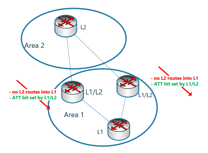
In this way, L1 routers only deliver traffic to the nearest L1/L2 router to send traffic outside the area.
But that’s not always the best solution. For example, if the area in question has more than one L1/L2 router, sometimes it is preferred to send the traffic to the L1/L2 router that is closer to the destination than to just send the traffic to the closest L1/L2 router.
This can happen when L1 routers know the address details and topologies connected to other areas. In other words, this is achieved when, contrary to the normal behavior of ISIS, prefixes are sent from L2 to L1.
Sending prefix from L2 to L1 is called Route Leaking.
Possible Loop created by ISIS Route Leaking
The possible problem that may be caused by route leaking is when the Area has more than one L1/L2 router.
In this case, the prefix sent from L2 to L1 by one of the L1/L2 routers will be returned to L2 by the other L1/L2 because the L1/L2 router cannot recognize that this prefix is created in the L1 domain. Or entered to the L1 domain from L2 domain, which ultimately leads to creating a loop.
This figure shows how a loop is created. The prefix 192.168.1.0/24 was entered into the L1 domain by one of the L1/L2 routers from the L2 domain and returned to the L2 domain by the other L1/L2 border router.

To fix this problem, ISIS considered a bit called UP/DOWN. When a prefix is sent from the L2 domain to L1, this bit is set by the L1/L2 router and therefore other L1/L2 routers stop sending the prefixes to the L2 domain whose UP/DOWN bit is set.
ISIS Route Leaking Configuration Example
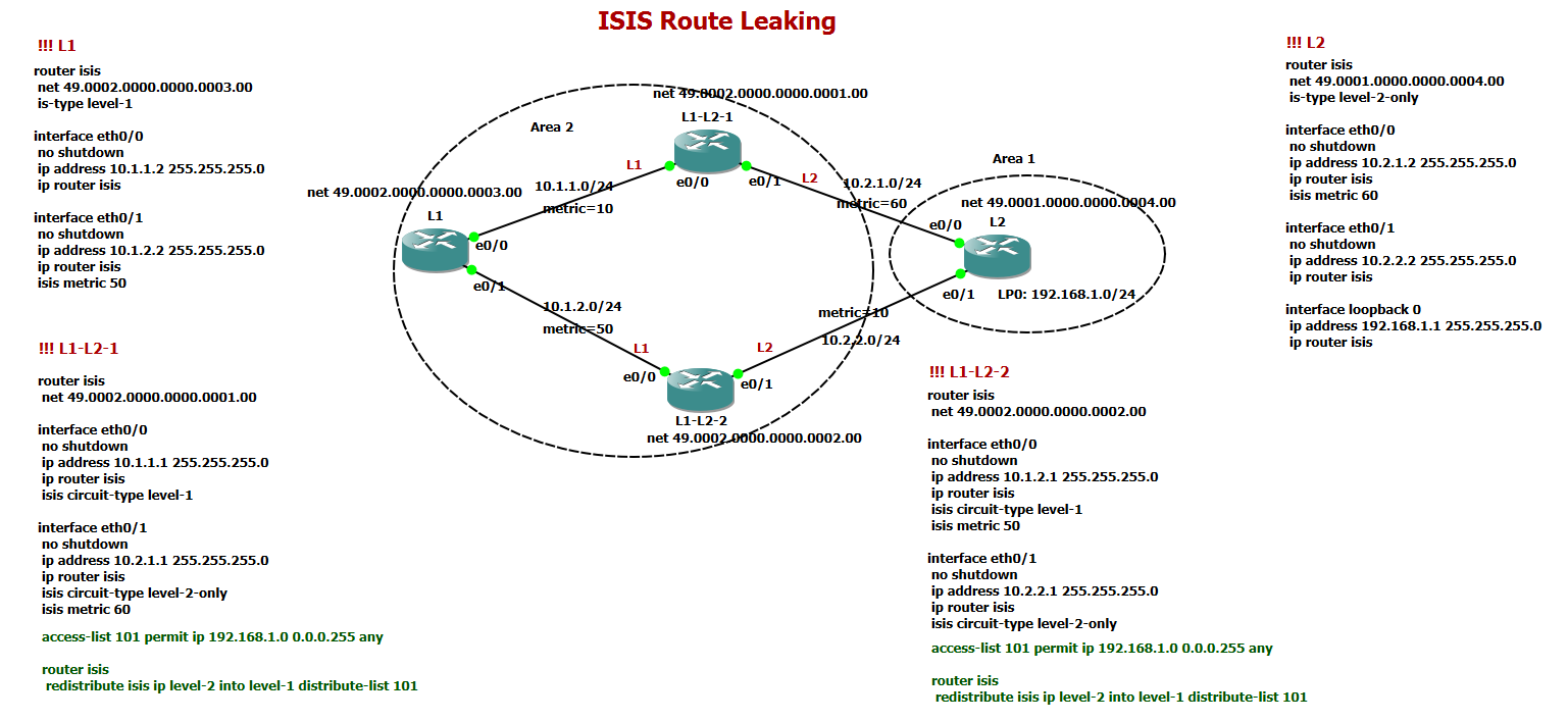
To better understand “route leaking”, look at to this topology where Area 2 has two L1/L2 border routers with Area 1.
The configuration is also displayed beside the topology. The configuration related to route leaking in both L1/L2 router is displayed larger and in green color.
But in the first step I copied all configurations except route leaking to compare when we have route leaking and when we don’t have route leaking.
The route leaking configuration will be explained shortly.
!!! L1
router isis
 net 49.0002.0000.0000.0003.00
 is-type level-1

interface eth0/0
 no shutdown
 ip address 10.1.1.2 255.255.255.0
 ip router isis

interface eth0/1
 no shutdown
 ip address 10.1.2.2 255.255.255.0
 ip router isis
 isis metric 50


!!! L1-L2-1
router isis
 net 49.0002.0000.0000.0001.00

interface eth0/0
 no shutdown
 ip address 10.1.1.1 255.255.255.0
 ip router isis
 isis circuit-type level-1

interface eth0/1
 no shutdown
 ip address 10.2.1.1 255.255.255.0
 ip router isis
 isis circuit-type level-2-only
 isis metric 60


!!! L1-L2-2
router isis
 net 49.0002.0000.0000.0002.00

interface eth0/0
 no shutdown
 ip address 10.1.2.1 255.255.255.0
 ip router isis
 isis circuit-type level-1
 isis metric 50

interface eth0/1
 no shutdown
 ip address 10.2.2.1 255.255.255.0
 ip router isis
 isis circuit-type level-2-only


!!! L2
router isis
 net 49.0001.0000.0000.0004.00
 is-type level-2-only

interface eth0/0
 no shutdown
 ip address 10.2.1.2 255.255.255.0
 ip router isis
 isis metric 60

interface eth0/1
 no shutdown
 ip address 10.2.2.2 255.255.255.0
 ip router isis

interface loopback 0
 ip address 192.168.1.1 255.255.255.0
 ip router isis
The internal routers in Area 2 have two routes to reach the destination network 192.168.1.0/24 in Area 1.
Also note that the metric of the two links between the L1 router and the second L1/L2 router, “L1_L2_2”, as well as the link between L2 and the first L1/L2 router, “L1_L2_1”, have been changed from the default value of 10 to the values of 50 and 60, respectively.
By default, the internal router of area 2 choose the first L1/L2 router, “L1_L2_1”, which is closest to the internal L1 router. This is because the metric to the first L1/L2 router is 10, but to the second L1/L2 router is 50.
But as you can see, the L1 router is closer to the destination through the second L1/L2 router “L1_L2_2” and not the first L1/L2 router.
The sum of the metric to the destination through the first L1/L2 router is 70, but through the second L1/L2 router is 60.
If we check router L1 routing table, it chooses the first L1/L2 router to enter Area 1.
L1#show ip route isis
...
Gateway of last resort is 10.1.1.1 to network 0.0.0.0

i*L1  0.0.0.0/0 [115/10] via 10.1.1.1, 00:03:02, Ethernet0/0
In order to reach Area 1, the default route is used, because by default no prefix information is transmitted from Area 1 to Area 2.
Both L1/L2 routers present themselves as border routers by setting the ATT bit and L1 routers chooses the first L1/L2 router as it is closer and has a lower metric.
If we check the output of L1 router database, you can see that both L1/L2 routers have set their ATT bit.
L1#show isis database

IS-IS Level-1 Link State Database:
LSPID                 LSP Seq Num  LSP Checksum  LSP Holdtime      ATT/P/OL
L1-L2-1.00-00         0x00000003   0x16CA        1017              1/0/0
L1-L2-1.01-00         0x00000001   0xAAA6        822               0/0/0
L1-L2-2.00-00         0x00000003   0xB2D8        1017              1/0/0
L1-L2-2.01-00         0x00000001   0xB09E        893               0/0/0
L1.00-00            * 0x00000005   0x4A1B        894               0/0/0
L1#
Configure Route Leaking is both L1/L2 Routers
Now we add route leaking configuration in both L1/L2 routers.
As you can see, route leaking configuration is a simple redistribution configuration. But instead of redistributing routes between two routing protocols, we redistribute routes from the L2 to the L1 domain.
First we configure an access-list to match the prefixes to be redistributed from level 2 into level 1.
In the second step, we configure redistribution from level 2 into level 1 with calling the access-list.
access-list 101 permit ip 192.168.1.0 0.0.0.255 any

router isis
 redistribute isis ip level-2 into level-1 distribute-list 101
After redistribution we check again the routing table of L1 router.
As you can see the route to prefix 192.168.1.0/24 is learned in router L1 and through the second L1/L2 router which is different from default route.
This is because the metric to reach the final destination 192.168.1.0/24 is closer through the second L1/L2 router.
L1#show ip route isis
...
Gateway of last resort is 10.1.1.1 to network 0.0.0.0

i*L1  0.0.0.0/0 [115/10] via 10.1.1.1, 00:05:42, Ethernet0/0
i ia  192.168.1.0/24 [115/198] via 10.1.2.1, 00:00:08, Ethernet0/1
L1#
You can see also router L1 database table to make sure that the prefix 192.168.1.0/24 is advertised through both L1/L2 routers.
L1#show isis database detail

IS-IS Level-1 Link State Database:
LSPID                 LSP Seq Num  LSP Checksum  LSP Holdtime      ATT/P/OL
L1-L2-1.00-00         0x00000004   0xAAFC        787               1/0/0
  Area Address: 49.0002
  NLPID:        0xCC
  Hostname: L1-L2-1
  IP Address:   10.1.1.1
  Metric: 10         IP 10.1.1.0 255.255.255.0
  Metric: 10         IS L1-L2-1.01
  Metric: 191        IP-Interarea 192.168.1.0 255.255.255.0
L1-L2-1.01-00         0x00000002   0xA8A7        972               0/0/0
  Metric: 0          IS L1-L2-1.00
  Metric: 0          IS L1.00
L1-L2-2.00-00         0x00000004   0xD5A7        787               1/0/0
  Area Address: 49.0002
  NLPID:        0xCC
  Hostname: L1-L2-2
  IP Address:   10.1.2.1
  Metric: 50         IP 10.1.2.0 255.255.255.0
  Metric: 50         IS L1-L2-2.01
  Metric: 148        IP-Interarea 192.168.1.0 255.255.255.0
L1-L2-2.01-00         0x00000002   0xAE9F        1179              0/0/0
  Metric: 0          IS L1-L2-2.00
  Metric: 0          IS L1.00
L1.00-00            * 0x00000007   0x461D        814               0/0/0
  Area Address: 49.0002
  NLPID:        0xCC
  Hostname: L1
  IP Address:   10.1.2.2
  Metric: 10         IP 10.1.1.0 255.255.255.0
  Metric: 50         IP 10.1.2.0 255.255.255.0
  Metric: 10         IS L1-L2-1.01
  Metric: 50         IS L1-L2-2.01
Thanks for sharing the knowledge. I have a query regarding metric advertisement by both L1-L2 routes.
L1-L2-1 is advertising 192.168.1.0/24 route with metric 191
L1-L2-2 is advertising 192.168.1.0/24 route with metric 148
did you manipulate the metric somewhere in network?
Regards
Sanjay Kumar