ISIS IPv6 Multi-Topology Configuration Example is the topic of this section.
With multi-topology, IPv4 and IPv6 have different topologies in the network and ISIS then has to run two SPF process for IPv4 and IPv6 to find the route to each IPv4 and IPv6 destination independently.
ISIS IPv6 Multi-Topology Fundamental
In today’s networks, all kinds of services are offered simultaneously. For example, IPV4, IPV6, and multicast services coexist in a network, and the topology of each service may be different from the other.
For example, if some network routers do not support IPv6. Or if we want multicast traffic to only go through certain routers in the network. In these examples, despite the fact that all three services are active on a shared network, the topology of each service differs from the other.
As you know, in ISIS and OSPF routing protocols, the SPF process runs on the topology and then extracts the best path.
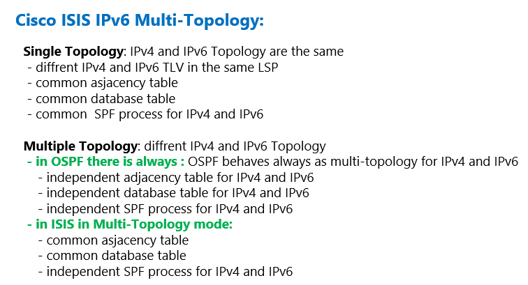
By default, ISIS is in single topology mode. This means that there is no separate SPF process for the IPV6 topology. Therefore, if the topology of IPv6 differs from IPv4, routing in IPv6 will have problems since the best routes are calculated and chosen based on the common topology.
OSPF protocol behaves always as multi-topology, in other words, IPv4 and IPv6 neighbors are created separately, and the database of each of them is kept separately from the other, and the SPF process is also run separately for IPV4 and IPV6.
However, this is not the case in the default ISIS protocol and it is assumed that the two IPV4 and IPV6 protocols have the same topology and therefore the same adjacency, database and SPF process are used.
But do not worry. ISIS also has this capability. If the IPv4 network topology is different from IPv6, you can use the Multi Topology feature in ISIS. With Multi Topology, it is no longer necessary for both IPV4 and IPV6 to have the same topology.
In this mode, ISIS works better and more efficiently than OSPF. Because even in the multi-topology there is no separate adjacency and database table for IPV4 and IPV6.
Hello packets and LSPs advertise each interface’s IPv4 and IPv6 capability by adding a label, and therefore, although IPv4 and IPv6 share a common database, each router knows what address types are supported by each of the network interfaces.
However, there are common adjacency and database tables for IPv4 and IPv6, but separate SPF processes are run for IPv4 and IPv6 topologies, and therefore an independent routing table is created for IPv4 and IPv6.
Single Topology ISIS in a Multi Topology Network Configuration Example
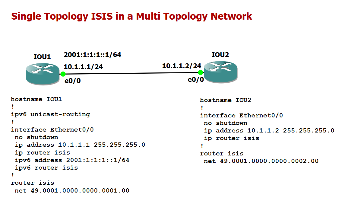
In this topology the routers IOU1 and IOU2 are connected directly to each other. In router IOU2 only IPv4 is configured, but both IPv4 and IPv6 are configured on the other side of the link on router IOU1.
A normal single topology ISIS is configured in this topology. The configuration is also displayed in the figure and there is no special configuration to explain.
!!! IOU1
ipv6 unicast-routing
!
interface Ethernet0/0
 no shutdown
 ip address 10.1.1.1 255.255.255.0
 ip router isis
 ipv6 address 2001:1:1:1::1/64
 ipv6 router isis
!
router isis
 net 49.0001.0000.0000.0001.00

!!! IOU2
interface Ethernet0/0
 no shutdown
 ip address 10.1.1.2 255.255.255.0
 ip router isis
!
router isis
 net 49.0001.0000.0000.0002.00
If we check adjacency in router IOU1, we can see that no adjacency is created between the routers IOU1 and IOU2.
This is because each of the routers sends IPv4 or IPv6 capabilities in the Hello packet, and if the capabilities between neighbors are not the same, the adjacency will not be created.
IOU1#show isis neighbors

System Id      Type Interface   IP Address      State Holdtime Circuit Id
IOU1#
The output of the command “debug is adj-packets ethernet 0/0” on router IOU1 shows that IPv6 is not active on the received Hello packet and does not match the router itself.
IOU1#debug isis adj-packets ethernet 0/0
IS-IS Adjacency related packets debugging is on for router process null
IOU1#
*Nov 19 13:04:59.424: ISIS-Adj: Rec L2 IIH from aabb.cc00.0200 (Ethernet0/0), cir type L1L2, cir id 0000.0000.0002.01, length 1497, ht(30)
*Nov 19 13:04:59.424: ISIS-Adj: No usable IPv6 linklocal addresses in LAN IIH from Ethernet0/0
IOU1#
*Nov 19 13:05:03.554: ISIS-Adj: Rec L1 IIH from aabb.cc00.0200 (Ethernet0/0), cir type L1L2, cir id 0000.0000.0002.01, length 1497, ht(30)
*Nov 19 13:05:03.554: ISIS-Adj: No usable IPv6 linklocal addresses in LAN IIH from Ethernet0/0
ISIS IPv6 Multi Topology Configuration Example
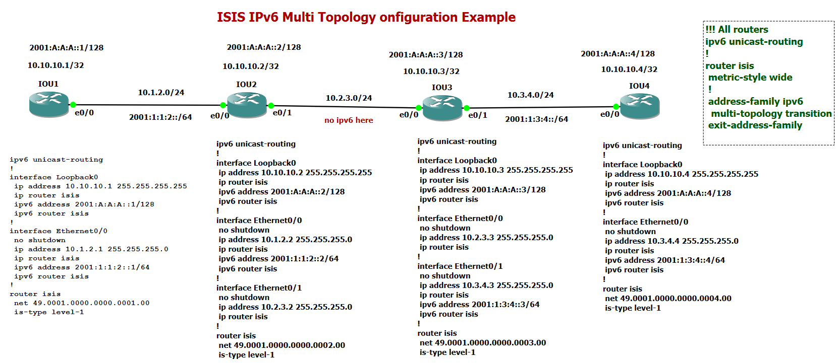
This figure shows a network where IPv6 and IPv4 have different topologies. Between the two routers IOU2 and IOU3 are only addressed with IPV4, but the rest of the links are addressed with both IPV4 and IPV6.
!!! IOU1
ipv6 unicast-routing
!
interface Loopback0
 ip address 10.10.10.1 255.255.255.255
 ip router isis
 ipv6 address 2001:A:A:A::1/128
 ipv6 router isis
!
interface Ethernet0/0
 no shutdown
 ip address 10.1.2.1 255.255.255.0
 ip router isis
 ipv6 address 2001:1:1:2::1/64
 ipv6 router isis
!
router isis
 net 49.0001.0000.0000.0001.00
 is-type level-1


!!! IOU2
ipv6 unicast-routing
!
interface Loopback0
 ip address 10.10.10.2 255.255.255.255
 ip router isis
 ipv6 address 2001:A:A:A::2/128
 ipv6 router isis
!
interface Ethernet0/0
 no shutdown
 ip address 10.1.2.2 255.255.255.0
 ip router isis
 ipv6 address 2001:1:1:2::2/64
 ipv6 router isis
!
interface Ethernet0/1
 no shutdown
 ip address 10.2.3.2 255.255.255.0
 ip router isis
!
router isis
 net 49.0001.0000.0000.0002.00
 is-type level-1

!!! IOU3
ipv6 unicast-routing
!
interface Loopback0
 ip address 10.10.10.3 255.255.255.255
 ip router isis
 ipv6 address 2001:A:A:A::3/128
 ipv6 router isis
!
interface Ethernet0/0
 no shutdown
 ip address 10.2.3.3 255.255.255.0
 ip router isis
!
interface Ethernet0/1
 no shutdown
 ip address 10.3.4.3 255.255.255.0
 ip router isis
 ipv6 address 2001:1:3:4::3/64
 ipv6 router isis
!
router isis
 net 49.0001.0000.0000.0003.00
 is-type level-1
In the first step, ISIS is configured in the usual single-topology mode. The configuration is shown in the figure. In right up side of the figure the configuration of multi topology is shown with a grean color which is not applied to the routers in this step.
And in this mode IPV4 and IPV6 addresses are only sent as two TLVs named IPV4 TLV Reachability and IPV6 TLV Reachability within the LSPs without compromising the integrity of the IPV4 check and IPV6 topology.
In the first step, ISIS is configured in the usual single topology mode. The configuration is shown in the figure. Interfaces with both IPv4 and IPv6 are configured with the “ip router isis” and “ipv6 router isis” commands. However, interfaces with only IPv4 addresses are only configured with only the “ip router isis” command, located between router IOU2 and IOU3.
The top right of the figure shows the multi-topology ISIS configuration with a green color, which is not applied to the routers in this step.
As you can see in the output of “show isis neighbors” and “show isis topology” commands, all neighbors have been created without any problems and without considering the difference between IPV6 and IPV4 topology.
IOU3#show isis neighbors

System Id      Type Interface   IP Address      State Holdtime Circuit Id
IOU2           L1   Et0/0       10.2.3.2        UP    25       IOU3.01
IOU4           L1   Et0/1       10.3.4.4        UP    9        IOU4.01

IOU3#show isis topology

IS-IS TID 0 paths to level-1 routers
System Id            Metric     Next-Hop             Interface   SNPA
IOU1                 20         IOU2                 Et0/0       aabb.cc00.0210
IOU2                 10         IOU2                 Et0/0       aabb.cc00.0210
IOU3                 --
IOU4                 10         IOU4                 Et0/1       aabb.cc00.0400
IOU3#
In such a situation, the IOU4 router learns the path to the IPv6 address connected with the IOU1 router. However, the communication with this address is not possible because part of the network only lets IPV4 traffic through.
In ISIS, IPv6 addresses are advertised based on IPV4 topology, regardless of the difference between IPV4 and IPV6 topology, and IPv6 addresses were considered only as topology leaves transmitted through TLV.
IOU4#show ipv6 route isis
IPv6 Routing Table - default - 9 entries
...
I1  2001:1:1:2::/64 [115/30]
     via FE80::A8BB:CCFF:FE00:310, Ethernet0/0
I1  2001:A:A:A::1/128 [115/40]
     via FE80::A8BB:CCFF:FE00:310, Ethernet0/0
I1  2001:A:A:A::2/128 [115/30]
     via FE80::A8BB:CCFF:FE00:310, Ethernet0/0
I1  2001:A:A:A::3/128 [115/20]
     via FE80::A8BB:CCFF:FE00:310, Ethernet0/0

IOU4#ping 2001:A:A:A::1
Type escape sequence to abort.
Sending 5, 100-byte ICMP Echos to 2001:A:A:A::1, timeout is 2 seconds:
UUUUU
Success rate is 0 percent (0/5)

IOU4#traceroute ipv6 2001:A:A:A::1
Type escape sequence to abort.
Tracing the route to 2001:A:A:A::1

  1 2001:1:3:4::3 !U  !U  !U
ISIS Multi Topology Configuration
To solve this problem, Multiple Topology ISIS must be activated in this network, in which case ISIS will create two different topologies, one for IPV4 and the other for IPV6.
To enable multiple topology, two commands are required on all routers. First, the metric type is changed to wide because the TLVs that transmit IPv6 information only use this type of metric. Second, we must enable Multiple Topology on all routers.
IOU4(config)#ipv6 unicast-routing
IOU4(config)#router isis
IOU4(config-router)#metric-style wide transition
IOU4(config-router)#address-family ipv6
IOU4(config-router-af)#multi-topology ?
  transition  Accept and generate both IS-IS IPv6 and Multi-topology IPv6 TLVs
  <cr>
IOU4(config-router-af)#multi-topology transition

!!! All routers
ipv6 unicast-routing
!
router isis
 metric-style wide
 !
 address-family ipv6
  multi-topology transition
 exit-address-family
In a few minutes, I will explain why the keyword transition is used at the end of multi-topology command.
It can be seen that after enabling Multiple Topology, two different topologies are created for IPv4 and IPv6. In such a situation, the topology table output shows that the IOU3 router can only create a path to reach the IPV6 networks connected to the IPU4 router and has no path to reach the IOU1 and IOU2 routers.
IOU3#show isis topology

IS-IS TID 0 paths to level-1 routers
System Id            Metric     Next-Hop             Interface   SNPA
IOU1                 20         IOU2                 Et0/0       aabb.cc00.0210
IOU2                 10         IOU2                 Et0/0       aabb.cc00.0210
IOU3                 --
IOU4                 10         IOU4                 Et0/1       aabb.cc00.0400
IOU3#
!
IOU3#show isis ipv6 topology

IS-IS TID 2 paths to level-1 routers
System Id            Metric     Next-Hop             Interface   SNPA
IOU1                 **
IOU2                 **
IOU3                 --
IOU4                 10         IOU4                 Et0/1       aabb.cc00.0400
IOU3#
using transition in multi-topology
Another point that should be noted is that all routers must be in Single-topology or multi-topology mode. If some network routers are in single-topology mode and some others in multi-topology mode, then the multi-topology routers will not recognize the capability of multi-topology routers in IPV6, which will result in the failure of proper routing of IPV6 traffic.
Now a question arises. To move ISIS from single-mode to multi-topology, we need to gradually move the routers from single- to multi-topology mode. In such a situation, some routers are in single-topology mode and some others are in multi-topology mode, resulting in incorrect routing
To solve the problem, we used the keyword „transition” at the end of the multi-topology command which allows a network operating in single-topology to continue to work while upgrading routers to multitopology mode. In transition mode, both types of TLVs (single-topology and multitopology) are sent in LSPs for all configured IPv6 addresses, but the router continues to operate in single-topology mode.