Cisco FTD Routed Mode is the option we chose to install FTD. In the last section we connected FTD and FMC in management-plane network. In this section we will bring FTD into the data path between LAN and Internet network. Interface configuration, configuring default gateway and basic NAT configuration are basic necessary configurations to add FTD to the path for inspecting data traffic.
Cisco FTD Routed Mode Topology
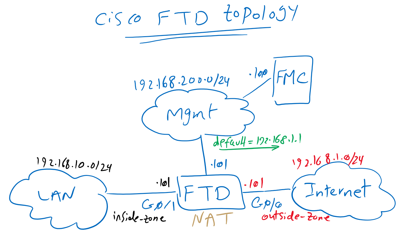
This is the topology that we have introduced in previous section. we have already configured management plane and bi-directional connectivity between FTD and FMC. but data plane part of FTD to inspect traffic between LAN and internet network will be configured in this section.
FTD can be configured in Routed Mode or Transparent mode and also inline mode and promiscuous mode that are related to IPS capability of FTD. Later we will discuss about deployment modes but now we are going to configure the routed mode since we chose this option in the first FTD installation step.
Three steps are the minimum configuration that we need to add FTD to inspect traffic between LAN and Internet connection.
First, interfaces must be configured. We will configure GigabitEthernet0/0 as outside interface and in outside-zone to be connected to the internet. IP address 192.168.1.101/24 will be configured in this interface.
Interface GigabitEthernet0/1 will be configured as inside interface in inside-zone to be connected to LAN network. IP address 192.168.10.101/24 will be configured in this interface.
In the second step, default route is configured in Cisco FTD so that FTD itself can communicate with the Internet.
The third step is to configure NAT so that endpoint on the LAN network can communicate with the Internet. In this section, a simple outside NAT is implemented. later we’ll have a special video to discuss more about NAT policies.
Cisco FTD Routed Mode configuration
let’s start with interface configuration.
Cisco FTD Interface configuration
enabling interface, giving a name and IP address are necessary to activate any interface but it is highly recommended that you also add a security zone for interfaces since some policies can be enabled between zones.
Devices -> Device Management -> choose FTD -> Edit
 Interfaces -> GigabitEthernet0/0 -> Edit
  General
   Name; outside
   Enabled: set
   Security Zone: New -> outside-zone
  IPV4
   IP Type: Use Static IP
   IP Address: 192.168.1.101/24

 Interfaces -> GigabitEthernet0/1 -> Edit
  General
   Name; inside
   Enabled: set
   Security Zone: New -> inside-zone
  IPV4
   IP Type: Use Static IP
   IP Address: 192.168.10.101/24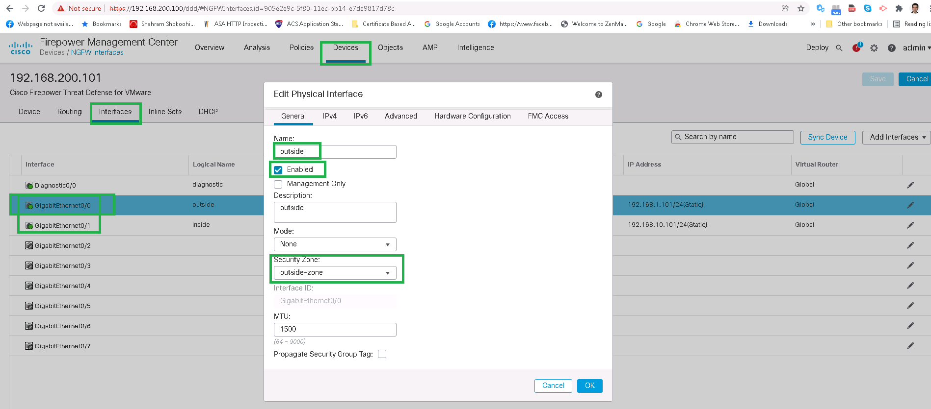

!!! do not forget to save and also deploy after every changes !!!
After interface configuration, you can also check the final status using the CLI command. the commands are exactly the same with Cisco ASA as it is actually Cisco ASA built into cisco FTD.
> show running-config interface
!
interface GigabitEthernet0/0
 description outside
 nameif outside
 security-level 0
 ip address 192.168.1.101 255.255.255.0
!
interface GigabitEthernet0/1
 description inside
 nameif inside
 security-level 0
 ip address 192.168.10.101 255.255.255.0
!
> show interface ip brief
Interface                  IP-Address      OK? Method Status                Protocol
GigabitEthernet0/0         192.168.1.101   YES manual up                    up
GigabitEthernet0/1         192.168.10.101  YES manual up                    up
GigabitEthernet0/2         unassigned      YES unset  administratively down up
GigabitEthernet0/3         unassigned      YES unset  administratively down up
GigabitEthernet0/4         unassigned      YES unset  administratively down up
GigabitEthernet0/5         unassigned      YES unset  administratively down up
GigabitEthernet0/6         unassigned      YES unset  administratively down up
GigabitEthernet0/7         unassigned      YES unset  administratively down up
Internal-Control0/0        127.0.1.1       YES unset  up                    up
Internal-Control0/1        unassigned      YES unset  up                    up
Internal-Data0/0           unassigned      YES unset  down                  up
Internal-Data0/0           unassigned      YES unset  up                    up
Internal-Data0/1           169.254.1.1     YES unset  up                    up
Internal-Data0/2           unassigned      YES unset  up                    up
Management0/0              unassigned      YES unset  up                    up
>
Cisco FTD default route configuration
In the second step, we configure default route in FTD so that the connection between FTD and the Internet is established. Our default gateway address 192.168.1.1.
Devices -> Device Management -> choose FTD -> Edit
 Routing -> Static Route -> Add Route
  Type: IPv4
  Interface: outside
  Selected Network: any-ipv4
  Gateway -> New
   Name: internet-gw
   host: 192.168.1.1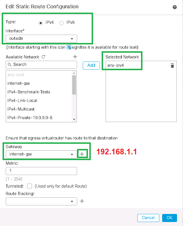
We can also check the default route created in Cisco FTD through the Cisco ASA/FTD CLI command.
> show running-config route
route outside 0.0.0.0 0.0.0.0 192.168.1.1 1
We check also the connectivity from FTD to the internet with ping command.
> ping 8.8.8.8
Please use 'CTRL+C' to cancel/abort...
Sending 5, 100-byte ICMP Echos to 8.8.8.8, timeout is 2 seconds:
!!!!!
Success rate is 100 percent (5/5), round-trip min/avg/max = 60/66/80 ms
>
Cisco FTD outside NAT (PAT) configuration
FTD is now connected to the internet but to connect LAN network behind FTD to the internet, it is necessary to enable NAT in cisco FTD.
Since some NAT scenarios will be discussed in a specific video. In this section we will not concentrate on NAT policies and only a simple source NAT/PAT configuration will be implemented so LAN endpoints can connect to the internet.
NAT must be configured from inside zone to outside zone. The IP subnet range 192.168.10.0/24 will be NAT to the interface in the outside zone in which the traffic goes out.
Devices -> NAT -> New Policy -> Threat Defense NAT
Name: FTD NAT Policy
Selected Devices: 192.168.200.101
Add Rule
NAT Rule: Auto NAT Rule
Type: Dynamic
Interface Objects
Source Interface Objects: inside-zone
Destination Interface Objects: outside-zone
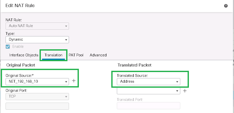
Translation
Original Source: -> Add
Name: NET_192_168_10
Network: 192.168.10.0/24
Translated Source: Address
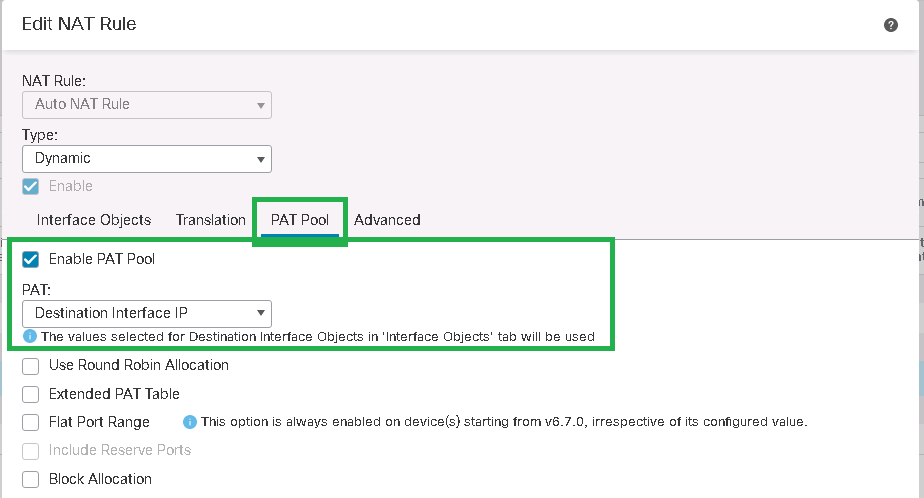
PAT Pool
Enable PAT Pool
PAT: Destination Interface IP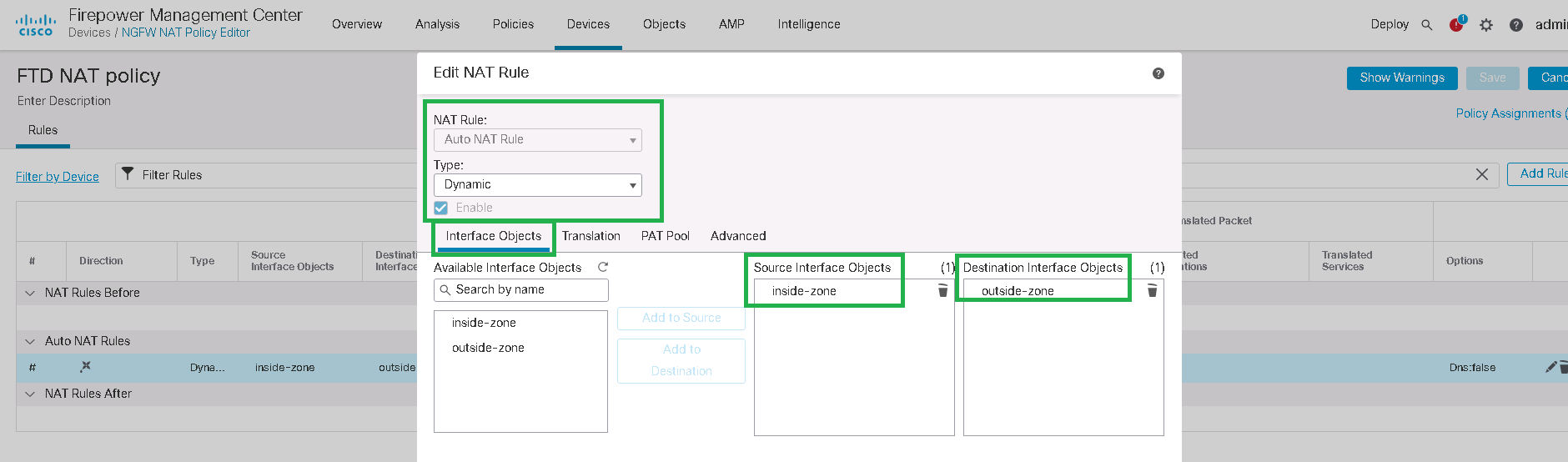
After NAT configuration, it can be check with “show running-config nat” command in cli mode.
> show running-config nat
!
object network NET_192_168_10
 nat (inside,outside) dynamic pat-pool interface
Also with “show nat” command, real nat hits can be checked.
> show nat

Auto NAT Policies (Section 2)
1 (inside) to (outside) source dynamic NET_192_168_10 pat-pool interface
    translate_hits = 167, untranslate_hits = 0
>