Juniper SRX route based IPsec VPN is another and preferred method of IPsec implementation that will be discussed in this section.
Policy based IPsec VPN is another method that we have implemented in the previous section.
Juniper SRX route based IPsec VPN configuration example
Juniper SRX route based IPsec VPN versus policy based
As we have discussed in the previous section, with route based IPsec implementation method, unlike policy based IPsec method, we configure a virtual interface for the tunnel.
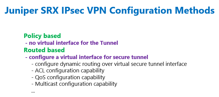
In route based IPsec configuration, unlike policy based IPsec configuration, in which we have sent interesting traffic to the IPsec VPN tunnel by configuring a policy, here, we send traffic to the IPsec VPN tunnel through static or dynamic routing.
Also we have discussed that with configuring a virtual interface for the IPsec tunnel, we can configure whatever features that we configure in normal interfaces.
For example, it is possible to configure dynamic or static routing through virtual tunnel interface, and ACL, QoS, multicasting and many other features within the virtual tunnel interface.
With policy based IPsec VPN, we don’t have most of these features.
Juniper SRX IPsec VPN topology
This is the topology that we will use in this section to configure route based IPsec VPN.
This is the same topology that we have used in the previous section for configuring policy based IPsec VPN.
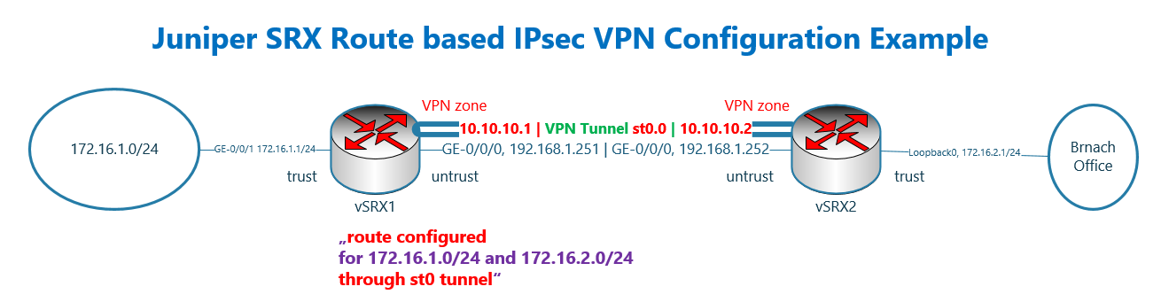
There are two juniper SRX devices with the name of vSRX1 and vSRX2.
These two device are connected to each other directly and through the interface ge-0/0/0, in the subnet 192.168.1.0/24 and in untrust zone. The IP address of vSRX1 is .251 and the other side .252.
vSRX1 is connected to LAN network through interface ge-0/0/1 and in the trust zone. The IP subnet 172.16.1.0/24 is configured for this network.
In vSRX2, the LAN interface in the trust zone is simulated using loopback interface and in the subnet 172.16.2.0/24.
The differences of the topology compare to the previous section are displayed with red colour.
We create a virtual interface for IPsec tunnel with the name of st0 and configure it in a new zone with the name of “VPN”.
Since a virtual interface is created for the IPsec tunnel, we are allowed to configure the IP address on each side of the IPsec VPN tunnel. One side is 10.10.10.1/24 and the other side is 10.10.10.2/24.
The other difference is that unlike policy based IPsec VPN configuration, in which we did not create any route to reach remote LAN network, here, we create a route to reach the remote LAN subnet through new tunnel interface.
Juniper SRX basic commands before IPsec VPN configuration
Before starting IPsec configuration, some basic configuration are already added into vSRX devices.
These are exactly what we have configured and explained in the previous section and here they are just repeated.
The hostname of device and IP address of interfaces are configured and interfaces are added to the appropriate zones according to the topology.
All system service and protocol traffic are permitted to vSRX devices with the host-inbound-traffic command.
I allowed “ike” in a separate line in the untrust interface. It wasn’t necessary here since I allowed all protocol and system service traffic.
I wanted only to show that for IPsec connectivity, we need to allow “ike” to the Juniper SRX devices.
Then we have two policies with the name of “default-permit” from untrust to trust zone and also from trust to untrust which permit everything.
set system host-name vSRX1
set interfaces ge-0/0/1 unit 0 family inet address 172.16.1.1/24
set interfaces ge-0/0/0 unit 0 family inet address 192.168.1.251/24

set security zones security-zone trust interfaces ge-0/0/1.0 host-inbound-traffic system-services all
set security zones security-zone trust interfaces ge-0/0/1.0 host-inbound-traffic protocols all
set security zones security-zone untrust interfaces ge-0/0/0.0 host-inbound-traffic system-services all
set security zones security-zone untrust interfaces ge-0/0/0.0 host-inbound-traffic system-services ike
set security zones security-zone untrust interfaces ge-0/0/0.0 host-inbound-traffic protocols all

set security policies from-zone trust to-zone untrust policy default-permit match source-address any
set security policies from-zone trust to-zone untrust policy default-permit match destination-address any
set security policies from-zone trust to-zone untrust policy default-permit match application any
set security policies from-zone trust to-zone untrust policy default-permit then permit

set security policies from-zone untrust to-zone trust policy default-permit match source-address any
set security policies from-zone untrust to-zone trust policy default-permit match destination-address any
set security policies from-zone untrust to-zone trust policy default-permit match application any
set security policies from-zone untrust to-zone trust policy default-permit then permit
set system host-name vSRX2
set interfaces lo0 unit 0 family inet address 172.16.2.1/24
set interfaces ge-0/0/0 unit 0 family inet address 192.168.1.252/24
set security zones security-zone trust interfaces lo0.0 host-inbound-traffic system-services all
set security zones security-zone trust interfaces lo0.0 host-inbound-traffic protocols all
set security zones security-zone untrust interfaces ge-0/0/0.0 host-inbound-traffic system-services all
set security zones security-zone untrust interfaces ge-0/0/0.0 host-inbound-traffic system-services ike
set security zones security-zone untrust interfaces ge-0/0/0.0 host-inbound-traffic protocols all
set security policies from-zone trust to-zone untrust policy default-permit match source-address any
set security policies from-zone trust to-zone untrust policy default-permit match destination-address any
set security policies from-zone trust to-zone untrust policy default-permit match application any
set security policies from-zone trust to-zone untrust policy default-permit then permit
set security policies from-zone untrust to-zone trust policy default-permit match source-address any
set security policies from-zone untrust to-zone trust policy default-permit match destination-address any
set security policies from-zone untrust to-zone trust policy default-permit match application any
set security policies from-zone untrust to-zone trust policy default-permit then permitJuniper SRX route based IPsec VPN basic configuration steps
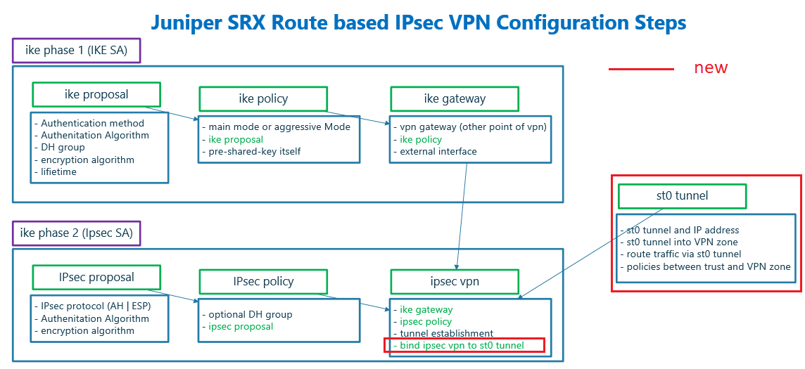
Here I have prepared a diagram which shows configuration steps of route based IPsec VPN.
This diagram is mostly similar to what we have shown and discussed in policy based VPN configuration. Therefore I will only explain the differences that I have distinguished with red color.
There are three steps to be configured to create an IPsec VPN.
- The first step is to create an IPsec virtual interface with the name of st0, assign the IP address, assign st0 interface to a brand new zone and create new policies between the new zone and existing zones.
- IKE phase 1 (IKE SA) to negotiate IKE security association. If you want to know the details of this phase, please look at the previous section.
- IKE phase 2 (IPsec SA) to negotiate IPsec security association. This section is also discussed in the previous section. What is new in this section is to bind configured tunnel interface to the IPsec VPN. So that IKE phase 1, IKE phase 2 and tunnel interface are tied to each other.
create virtual interface to route traffic over IPsec Tunnel
What is new and different in route based IPsec VPN is that in policy based IPsec VPN we configured policy to route interesting traffic through IPsec tunnel.
But in route based IPsec VPN configuration, we create a virtual IPsec tunnel interface with the name of st0 which is routable.
We can use static and also dynamic routing to route traffic between LAN subnets through tunnel interface. However we use here static routing to forward traffic over IPsec virtual tunnel interface.
We also must assign virtual tunnel interface to a zone. It can be assigned to existing untrust zone or to completely brand new zone. Here we assign new virtual tunnel interface to new VPN zone.
To allow traffic between LAN subnets through tunnel interface, st0, we have to allow interesting traffic between trust and VPN zone.
If you configure st0 interface into existing untrust zone, then interesting traffic must be added in existing policies between trust and untrust zone.
To tie configured virtual tunnel interface into existing IKE phase 1 and IKE phase 2, we will add a new command to bind st0 tunnel interface to IPsec VPN configuration. It is shown in the diagram with red colour.
Juniper SRX route based IPsec VPN basic configuration commands
These are the configuration that I have already prepared for route based IPsec VPN tunnel.
Most of the configuration are copy of the configurations that we have implemented and discussed in the previous section. Therefore only the new configurations will be discussed here.
In the first three lines, a new virtual tunnel interface, st0 is created. IP address is assigned to the interface and interface is assigned to a new VPN zone.
Then we create a static route to forward traffic with remote LAN destination through the tunnel.
IKE phase 1 and IKE phase 2 configurations has not changed and they are the same as policy based IPsec VPN configuration discussed in previous section.
The only change is to bind new virtual tunnel interface to the IPsec configuration which we configure with command “set security ipsec vpn vSRX1-vSRX2 bind-interface st0.0”. With this configuration virtual tunnel interface is tied to IKE phase 1 and phase 2 configurations.
We also have to create new polices between trust zone and new VPN zone to permit interesting traffic through tunnel.
Here we create two policies from zone trust to zone VPN and vice versa to permit everything between remote LAN subnets.
Now we can copy the configurations in vSRX1 and vSRX2.
set interfaces st0 unit 0 family inet address 10.10.10.1/24
set security zones security-zone VPN interfaces st0.0
set routing-options static route 172.16.2.0/24 next-hop st0.0

set security ike proposal IKE-PROPOSAL-1 authentication-method pre-shared-keys
set security ike proposal IKE-PROPOSAL-1 dh-group group2
set security ike proposal IKE-PROPOSAL-1 authentication-algorithm sha1
set security ike proposal IKE-PROPOSAL-1 encryption-algorithm aes-128-cbc
set security ike proposal IKE-PROPOSAL-1 lifetime-seconds 86400

set security ike policy IKE-POLICY1 mode main
set security ike policy IKE-POLICY1 proposals IKE-PROPOSAL-1 pre-shared-key ascii-text rayka-co.com

set security ike gateway vSRX2 ike-policy IKE-POLICY1
set security ike gateway vSRX2 address 192.168.1.252
set security ike gateway vSRX2 external-interface ge-0/0/0
set security ike gateway vSRX2 version v2-only

set security ipsec proposal IPSEC-PROPOSAL-1 protocol esp
set security ipsec proposal IPSEC-PROPOSAL-1 authentication-algorithm hmac-sha1-96
set security ipsec proposal IPSEC-PROPOSAL-1 encryption-algorithm aes-128-cbc

set security ipsec policy IPSEC-POLICY-1 perfect-forward-secrecy keys group2
set security ipsec policy IPSEC-POLICY-1 proposals IPSEC-PROPOSAL-1

set security ipsec vpn vSRX1-vSRX2 ike gateway vSRX2
set security ipsec vpn vSRX1-vSRX2 ike ipsec-policy IPSEC-POLICY-1
set security ipsec vpn vSRX1-vSRX2 establish-tunnels immediately
set security ipsec vpn vSRX1-vSRX2 bind-interface st0.0

set security address-book LOCAL address NET_172_16_1_0__24 172.16.1.0/24
set security address-book LOCAL attach zone trust

set security address-book REMOTE address NET_172_16_2_0__24 172.16.2.0/24
set security address-book REMOTE attach zone VPN

set security policies from-zone trust to-zone VPN policy TRUST-VPN-TRAFFIC match source-address NET_172_16_1_0__24
set security policies from-zone trust to-zone VPN policy TRUST-VPN-TRAFFIC match destination-address NET_172_16_2_0__24
set security policies from-zone trust to-zone VPN policy TRUST-VPN-TRAFFIC match application any
set security policies from-zone trust to-zone VPN policy TRUST-VPN-TRAFFIC then permit
insert security policies from-zone trust to-zone VPN policy TRUST-VPN-TRAFFIC before policy default-permit

set security policies from-zone VPN to-zone trust policy VPN-TRUST-TRAFFIC match source-address NET_172_16_2_0__24
set security policies from-zone VPN to-zone trust policy VPN-TRUST-TRAFFIC match destination-address NET_172_16_1_0__24
set security policies from-zone VPN to-zone trust policy VPN-TRUST-TRAFFIC match application any
set security policies from-zone VPN to-zone trust policy VPN-TRUST-TRAFFIC then permit
insert security policies from-zone VPN to-zone trust policy VPN-TRUST-TRAFFIC before policy default-permit

set security flow tcp-mss ipsec-vpn mss 1350
set interfaces st0 unit 0 family inet address 10.10.10.2/24
set security zones security-zone VPN interfaces st0.0
set routing-options static route 172.16.1.0/24 next-hop st0.0
set security ike proposal IKE-PROPOSAL-1 authentication-method pre-shared-keys
set security ike proposal IKE-PROPOSAL-1 dh-group group2
set security ike proposal IKE-PROPOSAL-1 authentication-algorithm sha1
set security ike proposal IKE-PROPOSAL-1 encryption-algorithm aes-128-cbc
set security ike proposal IKE-PROPOSAL-1 lifetime-seconds 86400
set security ike policy IKE-POLICY1 mode main
set security ike policy IKE-POLICY1 proposals IKE-PROPOSAL-1 pre-shared-key ascii-text rayka-co.com
set security ike gateway vSRX1 ike-policy IKE-POLICY1
set security ike gateway vSRX1 address 192.168.1.251
set security ike gateway vSRX1 external-interface ge-0/0/0
set security ike gateway vSRX1 version v2-only
set security ipsec proposal IPSEC-PROPOSAL-1 protocol esp
set security ipsec proposal IPSEC-PROPOSAL-1 authentication-algorithm hmac-sha1-96
set security ipsec proposal IPSEC-PROPOSAL-1 encryption-algorithm aes-128-cbc
set security ipsec policy IPSEC-POLICY-1 perfect-forward-secrecy keys group2
set security ipsec policy IPSEC-POLICY-1 proposals IPSEC-PROPOSAL-1
set security ipsec vpn vSRX2-vSRX1 ike gateway vSRX1
set security ipsec vpn vSRX2-vSRX1 ike ipsec-policy IPSEC-POLICY-1
set security ipsec vpn vSRX2-vSRX1 establish-tunnels immediately
set security ipsec vpn vSRX2-vSRX1 bind-interface st0.0
set security address-book LOCAL address NET_172_16_2_0__24 172.16.2.0/24
set security address-book LOCAL attach zone trust
set security address-book REMOTE address NET_172_16_1_0__24 172.16.1.0/24
set security address-book REMOTE attach zone VPN
set security policies from-zone trust to-zone VPN policy TRUST-VPN-TRAFFIC match source-address NET_172_16_2_0__24
set security policies from-zone trust to-zone VPN policy TRUST-VPN-TRAFFIC match destination-address NET_172_16_1_0__24
set security policies from-zone trust to-zone VPN policy TRUST-VPN-TRAFFIC match application any
set security policies from-zone trust to-zone VPN policy TRUST-VPN-TRAFFIC then permit
insert security policies from-zone trust to-zone VPN policy TRUST-VPN-TRAFFIC before policy default-permit
set security policies from-zone VPN to-zone trust policy VPN-TRUST-TRAFFIC match source-address NET_172_16_1_0__24
set security policies from-zone VPN to-zone trust policy VPN-TRUST-TRAFFIC match destination-address NET_172_16_2_0__24
set security policies from-zone VPN to-zone trust policy VPN-TRUST-TRAFFIC match application any
set security policies from-zone VPN to-zone trust policy VPN-TRUST-TRAFFIC then permit
insert security policies from-zone VPN to-zone trust policy VPN-TRUST-TRAFFIC before policy default-permit
set security flow tcp-mss ipsec-vpn mss 1350Monitoring and Troubleshooting route based IPsec VPN in Juniper SRX
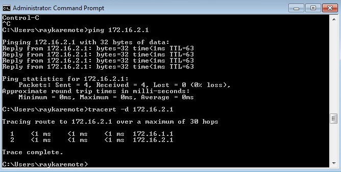
Now how we can test and monitor the IPsec VPN tunnel connectivity.
First we send traffic from subnet 172.16.1.0/24 to subnet 172.16.2.0/24 to make sure that the connectivity is established.
But to make sure we have some IPsec specific monitoring commands.
As we have discussed in the previous section, the commands starting with “show security ike”, are for monitoring of ike phase 1 negotiation and the commands starting with “show security ipsec” are for monitoring of ike phase 2 negotiation.
With command “show security ike security-associations” and “show security ike security-associations detail”, we monitor ike phase 1 negotiation.
rayka@vSRX1# run show security ike security-associations
Index   State  Initiator cookie  Responder cookie  Mode           Remote Address
3869997 UP     4e05a5974e9bfe00  bdcf51e4e0963fae  Main           192.168.1.252
The output must show that IKE phase 1 is UP. The details output also shows the parameters configured and negotiated in IKE phase 1.
The commands “show security ipsec security-associations” and “show security ipsec security-associations details” show the negotiation result of phase 2 negotiation.
[edit]
rayka@vSRX1# run show security ipsec security-associations
  Total active tunnels: 1     Total Ipsec sas: 2
  ID    Algorithm       SPI      Life:sec/kb  Mon lsys Port  Gateway
  <131073 ESP:aes-cbc-128/sha1 25ce8e3a 3509/ unlim - root 500 192.168.1.252
  >131073 ESP:aes-cbc-128/sha1 4ff90b19 3509/ unlim - root 500 192.168.1.252
  <131073 ESP:aes-cbc-128/sha1 97bb9ced 3532/ unlim - root 500 192.168.1.252
  >131073 ESP:aes-cbc-128/sha1 89b087b1 3532/ unlim - root 500 192.168.1.252


[edit]
rayka@vSRX1# run show security ipsec security-associations detail | grep st0
  DF-bit: clear, Copy-Outer-DSCP Disabled, Bind-interface: st0.0
In the output of these commands you can also make sure if phase 2 negotiation is successfully completed. You can also see the negotiated parameters and policy.
Still to make sure that traffic are forwarding through the IPsec tunnel, you can send traffic between two subnets and then with command “show security ipsec statistics”, make sure if the number of packets sending and receiving through IPsec Tunnel are increasing.
[edit]
rayka@vSRX1# run show security ipsec statistics
ESP Statistics:
  Encrypted bytes:             4560
  Decrypted bytes:             3960
  Encrypted packets:             38
  Decrypted packets:             33
AH Statistics:
  Input bytes:                    0
  Output bytes:                   0
  Input packets:                  0
  Output packets:                 0
Errors:
  AH authentication failures: 0, Replay errors: 0
  ESP authentication failures: 0, ESP decryption failures: 0
  Bad headers: 0, Bad trailers: 0
We can also check status of tunnel interface with “show interfaces terse” command.
[edit]
rayka@vSRX1# run show interfaces terse
Interface               Admin Link Proto    Local                 Remote
ge-0/0/0                up    up
ge-0/0/0.0              up    up   inet     192.168.1.251/24
...
st0                     up    up
st0.0                   up    up   inet     10.10.10.1/24
...
It is also possible to monitor routing table to make sure that traffic to remote LAN is routed through virtual tunnel interface.
rayka@vSRX1# run show route 172.16.2.1

inet.0: 10 destinations, 10 routes (10 active, 0 holddown, 0 hidden)
+ = Active Route, - = Last Active, * = Both

172.16.2.0/24      *[Static/5] 00:03:45
                    >  via st0.0
Good afternoon sir,
It was a pleasure to watch your video on how to make a route based site-to-site IPsec VPN. I follow your example an it work.
I have a few questions for you on any guidance on how to setup a route based site-to-site IPsec VPN with 2 LAN at each respective site.
Site A: LAN 1 & LAN 2
Site B: LAN 3 & LAN 4
During the IPsec LAN1 will connect to LAN 3, and LAN 2 will connect with LAN4. That would be in the static routing
I replicate the 1 LAN at each site example by changing the names in the policies and VPN zones. LAN 1 & 3 would be on st0.10 and LAN 2 & 4 would be on st0.11. all traffic of the tunnels are out of the same ge-0/0/0 on each device.
is that something that can be done?
Now I am seeing the state of the tunnels (at least one of them) is UP/DOWN. It s not stable.
I could share with you my topology and diagram for better visual.
I thank you in advance for any help that you can offer.
Hi
please send your topology and configuration. but it probably takes some time to check it.
thanks for your quick reply. what is the best email to send them (topology and code)to you?
Hello sir,
I have sent the topology and config (display set codes) files to the email sent by you to my account.
Thank you again,
Hello,
What is the importance of st0 interface ip 10.10.10.1/24 and 10.10.10.2/24 ,
does it requires to be reachable for each other.
Like any other L3 interface, they must have an IP address and it is important to be reachable, which is a sign that the tunnel is UP.
Thanks Majid,
In a lab environment it is easy to make these St0 IPs reachable to each other , but in a real world , the peer are distributed across the world on different public IPs, and making the st0 private ip reachable to each other is not possible , neither we can assign a public ip to st0 interface in the same series as that of WAN interface , as the firewall does not accepts two different interfaces to have ip address in the same series/subnet .
I think st0 ip address is only for representation.
enough to be reachable to each other not in the network. it is a sign of being UP