Cisco ISIS configuration example with a multi area topology is the discussion topic of this section.
Especially we will learn how to configure ISIS net address in multi area topology and how to configure router type and interface type between Level1 and Level2.
Cisco ISIS Multi Area Configuration Example
In the previous section we had an ISIS configuration example with only one area. Now we will configure ISIS in another topology but with more than one area.
Cisco ISIS Multi Area Topology
In this topology three areas exist and all areas are connected to other area. Connection between areas are established over the backbone path which is created by level2 routers.
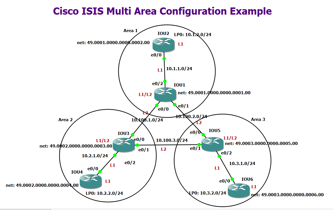
As you can see, three areas are connected via routers IOU1, IOU3 and IOU5, which form the backbone path. These three routers are of the type of L1/L2, which are connected to the inside of areas with L1 interfaces and to the backbone path through L2 interfaces.
Designing NET address in ISIS in a Multi Area Topology
To implement ISIS, a NET address must be configured on each router. The NET address must be configured in such a way that routers in different areas have different area numbers.
The system-id part of the NET address must be unique not only in the area but also in the entire network, otherwise you will receive a duplicate system-id message. This message appears only when you have entered the “debug isis adj-packet” command.
Configure the level of ISIS Router and Interfaces
As you can see in the figure, the Area boundary in ISIS is the link and not the router. Each router in ISIS is located in exactly one area.
ISIS routers are L1/L2 by default, in this case, two separate neighbors are created, one for L1 and the other for L2, between all neighboring routers.
To optimize ISIS, it is better to configure internal routers of an area of the type of L1 and border routers of the type L1/L2. Routers that are only in the backbone path and are not connected to any L1 router can be configured as L2 type.
This is the configuration of two routers, IOU1 and IOU2, as a sample.
IOU1(config-if)#isis circuit-type ?
  level-1       Level-1 only adjacencies are formed
  level-1-2     Level-1-2 adjacencies are formed
  level-2-only  Level-2 only adjacencies are formed
  <cr>
!!! IOU1
router isis
net 49.0001.0000.0000.0001.00
!
interface Ethernet0/0
no shutdown
ip address 10.100.1.1 255.255.255.0
ip router isis
isis circuit-type level-2-only
!
interface Ethernet0/1
no shutdown
ip address 10.100.2.1 255.255.255.0
ip router isis
isis circuit-type level-2-only
!
interface Ethernet0/2
no shutdown
ip address 10.1.1.1 255.255.255.0
ip router isis
isis circuit-type level-1!!! IOU2
router isis
net 49.0001.0000.0000.0002.00
is-type level-1
passive-interface Loopback0
!
interface Ethernet0/0
no shutdown
ip address 10.1.1.2 255.255.255.0
ip router isis
!
interface Loopback0
ip address 10.1.2.2 255.255.255.0
ip router isis!!! IOU3
router isis
net 49.0002.0000.0000.0003.00
!
interface Ethernet0/0
no shutdown
ip address 10.100.1.3 255.255.255.0
ip router isis
isis circuit-type level-2-only
!
interface Ethernet0/1
no shutdown
ip address 10.100.3.3 255.255.255.0
ip router isis
isis circuit-type level-2-only
!
interface Ethernet0/2
no shutdown
ip address 10.2.1.3 255.255.255.0
ip router isis
isis circuit-type level-1
!!! IOU4
router isis
net 49.0002.0000.0000.0004.00
is-type level-1
passive-interface Loopback0
!
interface Ethernet0/0
no shutdown
ip address 10.2.1.4 255.255.255.0
ip router isis
!
interface Loopback0
ip address 10.2.2.4 255.255.255.0
ip router isis
!!! IOU5
router isis
net 49.0003.0000.0000.0005.00
!
interface Ethernet0/0
no shutdown
ip address 10.100.2.5 255.255.255.0
ip router isis
isis circuit-type level-2-only
!
interface Ethernet0/1
no shutdown
ip address 10.100.3.5 255.255.255.0
ip router isis
isis circuit-type level-2-only
!
interface Ethernet0/2
no shutdown
ip address 10.3.1.5 255.255.255.0
ip router isis
isis circuit-type level-1
!!! IOU6
router isis
net 49.0003.0000.0000.0006.00
is-type level-1
passive-interface Loopback0
!
interface Ethernet0/0
no shutdown
ip address 10.3.1.6 255.255.255.0
ip router isis
!
interface Loopback0
ip address 10.3.2.6 255.255.255.0
ip router isisAs shown in the configuration, the type of being L1 or L2 is configured at the interface level in the router IOU1 with the command “isis circuit-type level-1 | level-1-2 | level-2-only“. By default it is level-1-2.
Interfaces ethernet0/0 and ethernet0/1 connected to the backbone path are configured as L2. Interface ethernet0/2 connected to the inside of area is configured as L1.
It is better to make changes always in L1/L2 routers. Therefore internal interfaces are configured as L1 and interfaces connected to backbone path be configured as L2. Otherwise, these routers create two separate neighbors on each interface, one for L1 and one for L2.
in router IOU2 unlike IOU1, when you configure a router at “router isis“ level with the is-type command as L1, then all interfaces of the router will automatically be L1 and you do not need to configure them at the interface level.
This is also true for L2 only routers. A router that is only configured as L2, automatically all its interfaces will be L2 and does not need to be reconfigured.
Another point to keep in mind when configuring ISIS is that the system ID in the “net address” must be unique not just within the area, but throughout the network.
ISIS Monitoring and Troubleshooting Commands
The routing table of two routers IOU1 and IOU2 can be checked with “show ip route isis” command.
As you can seem there is only one default route in the routing table of router IOU2. In ISIS, L1/L2 border routers only send the default route to level1 routers, which is the same as the totally stub area in the OSPF protocol.
IOU2#show ip route isis
Codes: L - local, C - connected, S - static, R - RIP, M - mobile, B - BGP
       D - EIGRP, EX - EIGRP external, O - OSPF, IA - OSPF inter area
       N1 - OSPF NSSA external type 1, N2 - OSPF NSSA external type 2
       E1 - OSPF external type 1, E2 - OSPF external type 2
       i - IS-IS, su - IS-IS summary, L1 - IS-IS level-1, L2 - IS-IS level-2
       ia - IS-IS inter area, * - candidate default, U - per-user static route
       o - ODR, P - periodic downloaded static route, H - NHRP, l - LISP
       a - application route
       + - replicated route, % - next hop override

Gateway of last resort is 10.1.1.1 to network 0.0.0.0

i*L1  0.0.0.0/0 [115/10] via 10.1.1.1, 00:02:02, Ethernet0/0
IOU2#
If you are interested in leaking part or all of the routes of other areas into the routing table of L1 routers, you should use the “route leaking” feature, which we will talk about in the next sections.
Unlike router IOU2, the router IOU1, which is of both L1/L2, has learned the route of all networks.
IOU1#show ip route isis
Codes: L - local, C - connected, S - static, R - RIP, M - mobile, B - BGP
       D - EIGRP, EX - EIGRP external, O - OSPF, IA - OSPF inter area
       N1 - OSPF NSSA external type 1, N2 - OSPF NSSA external type 2
       E1 - OSPF external type 1, E2 - OSPF external type 2
       i - IS-IS, su - IS-IS summary, L1 - IS-IS level-1, L2 - IS-IS level-2
       ia - IS-IS inter area, * - candidate default, U - per-user static route
       o - ODR, P - periodic downloaded static route, H - NHRP, l - LISP
       a - application route
       + - replicated route, % - next hop override

Gateway of last resort is not set

      10.0.0.0/8 is variably subnetted, 12 subnets, 2 masks
i L1     10.1.2.0/24 [115/20] via 10.1.1.2, 00:02:42, Ethernet0/2
i L2     10.2.1.0/24 [115/20] via 10.100.1.3, 00:02:27, Ethernet0/0
i L2     10.2.2.0/24 [115/30] via 10.100.1.3, 00:02:09, Ethernet0/0
i L2     10.3.1.0/24 [115/20] via 10.100.2.5, 00:02:00, Ethernet0/1
i L2     10.3.2.0/24 [115/30] via 10.100.2.5, 00:01:42, Ethernet0/1
i L2     10.100.3.0/24 [115/20] via 10.100.2.5, 00:02:00, Ethernet0/1
                       [115/20] via 10.100.1.3, 00:02:00, Ethernet0/0
IOU1#
Routes learned through internal interfaces and L1 neighbors are labeled as L1, and routes learned through external interfaces and L2 neighbor routers are labeled as L2 in the routing table.
You can see the neighbor table with the command “show isis neighbors”.
The neighbor table of router IOU1 shows that this router has L1 neighborship with IOU2 routers and L2 neighborship with IOU3 and IOU5 routers.
IOU1#show isis neighbors

System Id      Type Interface   IP Address      State Holdtime Circuit Id
IOU2           L1   Et0/2       10.1.1.2        UP    9        IOU2.01
IOU3           L2   Et0/0       10.100.1.3      UP    8        IOU3.01
IOU5           L2   Et0/1       10.100.2.5      UP    7        IOU5.01
IOU1#
You can see the database table with the command “show isis database”.
The database table in router IOU1 shows that this protocol keeps two independent databases, one for L1 and one for L2.
IOU1#show isis database

IS-IS Level-1 Link State Database:
LSPID                 LSP Seq Num  LSP Checksum  LSP Holdtime      ATT/P/OL
IOU1.00-00          * 0x00000004   0x1833        1030              1/0/0
IOU2.00-00            0x00000003   0x06A7        1007              0/0/0
IOU2.01-00            0x00000001   0x7CD6        1008              0/0/0
IS-IS Level-2 Link State Database:
LSPID                 LSP Seq Num  LSP Checksum  LSP Holdtime      ATT/P/OL
IOU1.00-00          * 0x00000005   0x9F72        1051              0/0/0
IOU3.00-00            0x00000004   0x1DE9        1049              0/0/0
IOU3.01-00            0x00000001   0x14C3        1024              0/0/0
IOU5.00-00            0x00000003   0x9F5C        1070              0/0/0
IOU5.01-00            0x00000001   0x20B3        1050              0/0/0
IOU5.02-00            0x00000001   0x4B85        1050              0/0/0
IOU1#
The L1 database contains information learned from L1 neighbors, and the L2 database also contains information learned through L2 neighbors.
Another point you can see in the output of database table is the value 1 in the ATT bit in some database entries.
In this way, the L1/L2 routers inform the L1 routers that they are the exit point from the Area, and therefore the L1 routers identify their default route to destination outside of the Area.