Cisco ISIS configuration example with a single area is the discussion topic of this section.
We will learn how to enable ISIS routing protocol, configure net address, activate ISIS on the interfaces and change the type of ISIS router as level1 or level2.
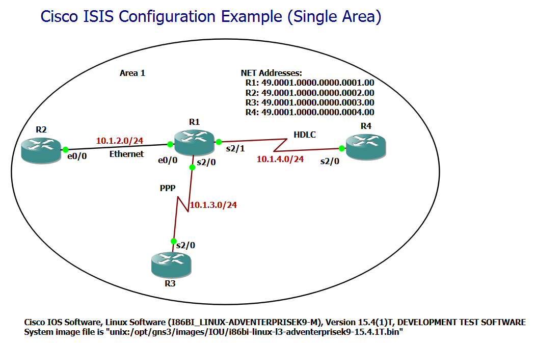
Cisco ISIS Configuration Example (Single Area)
Now that you are familiar with the basic concepts of ISIS routing protocol and assume that you already know OSPF concepts and configuration, it is now time to configure ISIS in a simple single-area topology and get to know a little about basic Cisco ISIS configuration.
!!! R1
router isis
 net 49.0001.0000.0000.0001.00
 is-type level-1
!
interface Ethernet0/0
 no shutdown
 ip address 10.1.2.1 255.255.255.0
 ip router isis
interface Serial2/0
 no shutdown
 encapsulation ppp
 ip address 10.1.3.1 255.255.255.0
 ip router isis
interface Serial2/1
 no shutdown
 encapsulation hdlc
 ip address 10.1.4.1 255.255.255.0
 ip router isis

!!! R2
router isis
 net 49.0001.0000.0000.0002.00
 is-type level-1
!
interface Ethernet0/0
 no shutdown
 ip address 10.1.2.2 255.255.255.0
 ip router isis


!!! R3
router isis
 net 49.0001.0000.0000.0003.00
 is-type level-1
!
interface Serial2/0
 no shutdown
 encapsulation ppp
 ip address 10.1.3.3 255.255.255.0
 ip router isis


!!! R4
router isis
 net 49.0001.0000.0000.0004.00
 is-type level-1
!
interface Serial2/0
 no shutdown
 encapsulation hdlc
 ip address 10.1.4.4 255.255.255.0
 ip router isis
Cisco ISIS Single Area Basic Configuration Example
To start, consider the topology and basic configuration of the ISIS protocol. There are some points that are important to notice in this scenario:
- All routers in this scenario are in the same area. In the next section we will implement another scenario where there is more than one area.
- To enable the ISIS routing protocol in the router, we use the command “router isis“.
- To activate ISIS routing protocol in interfaces, unlike all other IGP protocols, we do not use the network command, but we use the “ip router isis” command in the context of the interface itself.
- As already mentioned, all ISIS routers must have a CLNS address, or more accurate a NET address. The format of the NET address has already been discussed in the previous section.
- In this scenario, there is only one area and the area number is 0001. The system ID is a unique 6-byte value for each router. You can check the system ID of each router with the “show isis hostname” command. The NSEL value is always 00.
- By default, all ISIS routers and interfaces are of type L1/L2. In the scenario where there is only one area, either L1 or L2 type is enough to be configured and there is not much difference between L1 and L2. Therefore, in this scenario, with the command “is-type level-1“, all routers are configured as L1.
- When the router is-type as only L1 or L2 is configured, then the level of all of its interfaces are also determined according to the router is-type.
- In this scenario, if you leave all routers as L1/L2, no problem will arise, but two separate neighbors will be created, one with L1 and the other with L2. Also two separate databases L1 and L2 are created in each of the routers. Therefore the resources are not used optimally.
R1#show isis hostname
Level  System ID      Dynamic Hostname  (notag)
     * 0000.0000.0001 R1
 1     0000.0000.0002 R2
 1     0000.0000.0003 R3
 1     0000.0000.0004 R4
Cisco ISIS Monitoring and Troubleshooting
After initial configuration, the most important monitoring commands are “show isis neighbors“, “show isis topology“, and “show isis database“, which show the neighbor table, topology table, and database table, respectively.
The list of directly connected neighbors for each router are shown in the neighbor table.
R1#show isis neighbors

System Id      Type Interface   IP Address      State Holdtime Circuit Id
R2             L1   Et0/0       10.1.2.2        UP    9        R2.01
R3             L1   Se2/0       10.1.3.3        UP    23       00
R4             L1   Se2/1       10.1.4.4        UP    25       00
R1#
The topology table shows the list of all routers in all areas.
R1#show isis topology

IS-IS TID 0 paths to level-1 routers
System Id            Metric     Next-Hop             Interface   SNPA
R1                   --
R2                   10         R2                   Et0/0       aabb.cc00.0200
R3                   10         R3                   Se2/0       *PPP*
R4                   10         R4                   Se2/1       *HDLC*
To check the details of LSPs in ISIS, we check the database table.
R1#show isis database

IS-IS Level-1 Link State Database:
LSPID                 LSP Seq Num  LSP Checksum  LSP Holdtime      ATT/P/OL
R1.00-00            * 0x00000005   0x63A4        1199              0/0/0
R2.00-00              0x00000002   0x549B        696               0/0/0
R2.01-00              0x00000001   0x7CD6        696               0/0/0
R3.00-00              0x00000002   0x3FAD        696               0/0/0
R4.00-00              0x00000002   0xE631        695               0/0/0
R1#
R1#show isis database verbose

IS-IS Level-1 Link State Database:
LSPID                 LSP Seq Num  LSP Checksum  LSP Holdtime      ATT/P/OL
R1.00-00            * 0x00000005   0x63A4        1196              0/0/0
  Area Address: 49.0001
  NLPID:        0xCC
  Hostname: R1
  IP Address:   10.1.4.1
  Metric: 10         IP 10.1.2.0 255.255.255.0
  Metric: 10         IP 10.1.3.0 255.255.255.0
  Metric: 10         IP 10.1.4.0 255.255.255.0
  Metric: 10         IS R2.01
  Metric: 10         IS R3.00
R2.00-00              0x00000002   0x549B        693               0/0/0
  Area Address: 49.0001
  NLPID:        0xCC
  Hostname: R2
  IP Address:   10.1.2.2
  Metric: 10         IP 10.1.2.0 255.255.255.0
  Metric: 10         IS R2.01
R2.01-00              0x00000001   0x7CD6        693               0/0/0
  Metric: 0          IS R2.00
  Metric: 0          IS R1.00
R3.00-00              0x00000002   0x3FAD        693               0/0/0
  Area Address: 49.0001
  NLPID:        0xCC
  Hostname: R3
  IP Address:   10.1.3.3
  Metric: 10         IP 10.1.3.0 255.255.255.0
  Metric: 10         IS R1.00
R4.00-00              0x00000003   0x535B        1193              0/0/0
  Area Address: 49.0001
  NLPID:        0xCC
  Hostname: R4
  IP Address:   10.1.4.4
  Metric: 10         IP 10.1.4.0 255.255.255.0
R1#
We will discuss the details of neighbor table, topology table and especially database table and LSP details in the next sections.