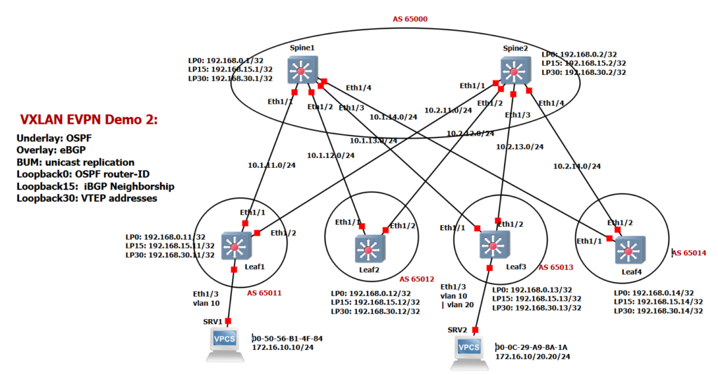
There are a few differences in this example compared to the first example. We are using three loopback interfaces, loopback0 with subnet 192.168.0.x for OSPF router-id , loopback15 with subnet 192.168.1.5.x for BGP neighborship and loopback30 with subnet 192.168.30.x as the VTEP address for VXLAN tunnel termination. In this demonstration we are not using iBGP, but rather eBGP as the overlay protocol. Spine switches have their own AS number which is 65000 in this topology. Each leaf switch also has its own AS number which are from 65011 to 65014. In this Example We don’t enable multicast routing, we use the unicast replication method instead to forward BUM traffic.

Configuration Example 2 is displayed in 9 Steps.
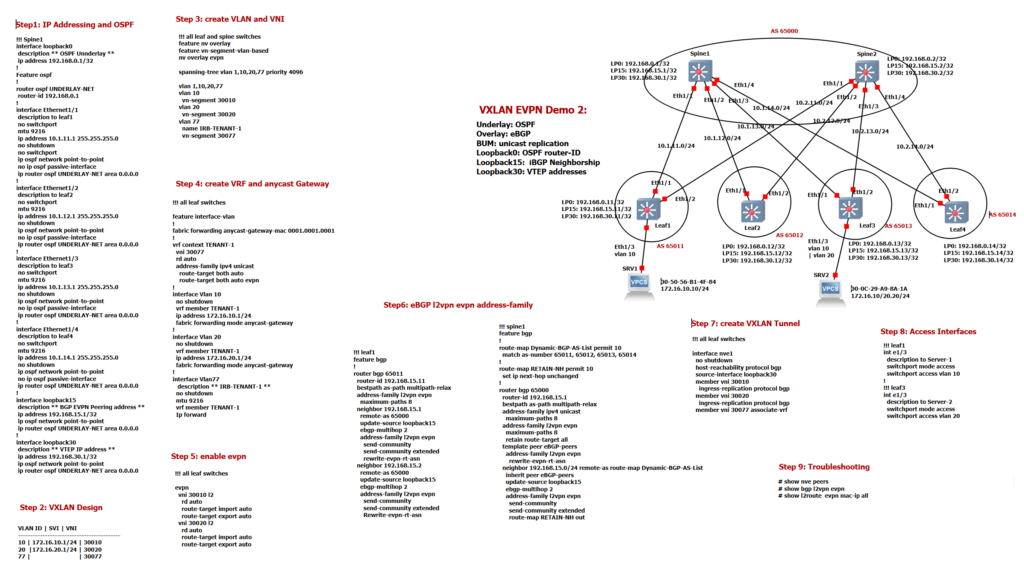
Step1: IP Addressing and OSPF
The first step is IP addressing and OSPF configuration. The configuration of Spine1 is shown here as an example. Loopback0 is used for the OSPF router ID and is not enabled in the OSPF routing protocol. The point-to-point network type is used in the interfaces to avoid DR / BDR selection. You can use the “show ip ospf neighbor” command and also ping command to ensure that network communication is established.
!!! Spine1
hostname spine1
!
interface loopback0
 description ** OSPF Unnderlay **
 ip address 192.168.0.1/32
!
Feature ospf
!
router ospf UNDERLAY-NET
 router-id 192.168.0.1
!
interface Ethernet1/1
 description to leaf1
 no switchport
 mtu 9216
 ip address 10.1.11.1 255.255.255.0
 no shutdown
 no switchport
 ip ospf network point-to-point
 no ip ospf passive-interface
 ip router ospf UNDERLAY-NET area 0.0.0.0
!
interface Ethernet1/2
 description to leaf2
 no switchport
 mtu 9216
 ip address 10.1.12.1 255.255.255.0
 no shutdown
 ip ospf network point-to-point
 no ip ospf passive-interface
 ip router ospf UNDERLAY-NET area 0.0.0.0
!
interface Ethernet1/3
 description to leaf3
 no switchport
 mtu 9216
 ip address 10.1.13.1 255.255.255.0
 no shutdown
 ip ospf network point-to-point
 no ip ospf passive-interface
 ip router ospf UNDERLAY-NET area 0.0.0.0
!
interface Ethernet1/4
 description to leaf4
 no switchport
 mtu 9216
 ip address 10.1.14.1 255.255.255.0
 no shutdown
 ip ospf network point-to-point
 no ip ospf passive-interface
 ip router ospf UNDERLAY-NET area 0.0.0.0
!
interface loopback15
 description ** BGP EVPN Peering address **
 ip address 192.168.15.1/32
 ip ospf network point-to-point
 ip router ospf UNDERLAY-NET area 0.0.0.0
!
interface loopback30
 description ** VTEP IP address **
 ip address 192.168.30.1/32
 ip ospf network point-to-point
 ip router ospf UNDERLAY-NET area 0.0.0.0
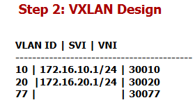
Step2: VXLAN Design
The second step shows VXLAN Design. We have three VLANs, VLAN 10, VLAN 20 and VLAN 77. VLAN 10 and VLAN 20 are mapped to L2 VNI 30010 and 30020 for L2 communication. VLAN 77 is mapped to L3 VNI 30077, which is used for inter-VXLAN routing.
Step3: create VLAN and VNI
in Step 3, the VXLAN function is enabled with three commands. then VLAN and the corresponding VNI are configured in all leaf switches. VLAN 10 is mapped to L2 VNI 30010. VLAN 20 is mapped to L2 VNI 30020 and VLAN 77 is mapped to L3 VNI 30077. Also, Spanning Tree is configured so that when the VXLAN network is connected to a traditional network, it is the root of the network.
!!!all leaf switches
feature nv overlay
feature vn-segment-vlan-based
nv overlay evpn
!
spanning-tree vlan 1,10,20,77 priority 4096
!
fabric forwarding anycast-gateway-mac 0001.0001.0001
!
vlan 10,20,77
vlan 10
  vn-segment 30010
vlan 20
  vn-segment 30020
vlan 77
  name IRB-TENANT-1
  vn-segment 30077
Step4: create VRF and anycast Gateway
In step 4 the anycast gateway is configured in all leaf switches. Interface-Vlan 10 and Interface-Vlan 20 with the anycast addresses 172.16.10.1 and 172.16.20.1 are configured in all leaf switches. All interface Vlans are members of VRF TENANT-1. The gateway MAC address is also configured as an anycast address. Anycast MAC address is the same for all VLANs.
!!! all leaf switches
feature interface-vlan

!
fabric forwarding anycast-gateway-mac 0001.0001.0001
!

vrf context TENANT-1
  vni 30077
  rd auto
  address-family ipv4 unicast
    route-target both auto
    route-target both auto evpn
!
interface Vlan 10
  no shutdown
  vrf member TENANT-1
  ip address 172.16.10.1/24
  fabric forwarding mode anycast-gateway
!
interface Vlan 20
  no shutdown
  vrf member TENANT-1
  ip address 172.16.20.1/24
  fabric forwarding mode anycast-gateway
!
interface Vlan77
   description ** IRB-TENANT-1 **
  no shutdown
  mtu 9216
  vrf member TENANT-1
  Ip forward
Step 5: enable EVPN
In step 5, L2 VNI 30010 and 30020 are activated in EVPN. RD and RT are configured as auto in both EVPN and also in VRF modes. We have already spoken several times about the concept of RD and RT.
!!! all leaf switches
evpn
  vni 30010 l2
    rd auto
    route-target import auto
    route-target export auto
  vni 30020 l2
    rd auto
    route-target import auto
    route-target export auto
Step 6: eBGP EVPN overlay protocol
In Step6 the BGP Overly protocol is activated with the evpn address family. The configuration of leaf1 and spine1 is displayed here. There are a few points about implementing eBGP instead of iBGP.
As you can see in the topology, routes are advertised between the leaf switch through Spine BGP route server. This is to reduce the number of BGP neighbours directly between leaf switches, especially when the number of leaf switches is more than a few.
!!! spine1
feature bgp
feature nv overlay
feature vn-segment-vlan-based
nv overlay evpn
!
route-map Dynamic-BGP-AS-List permit 10
  match as-number 65011, 65012, 65013, 65014
!
route-map RETAIN-NH permit 10
  set ip next-hop unchanged
!
router bgp 65000
  router-id 192.168.15.1
  bestpath as-path multipath-relax
  address-family ipv4 unicast
    maximum-paths 8
  address-family l2vpn evpn
    maximum-paths 8
    retain route-target all
  template peer eBGP-peers
    address-family l2vpn evpn
      rewrite-evpn-rt-asn
  neighbor 192.168.15.0/24 remote-as route-map Dynamic-BGP-AS-List
    inherit peer eBGP-peers
    update-source loopback15
    ebgp-multihop 2
    address-family l2vpn evpn
      send-community
      send-community extended
      route-map RETAIN-NH out
!
!!! leaf1
feature bgp
feature nv overlay
feature vn-segment-vlan-based
nv overlay evpn
!
router bgp 65011
  router-id 192.168.15.11
  bestpath as-path multipath-relax
  address-family l2vpn evpn
    maximum-paths 8
  neighbor 192.168.15.1
    remote-as 65000
    update-source loopback15
    ebgp-multihop 2
    address-family l2vpn evpn
      send-community
      send-community extended
      rewrite-evpn-rt-asn
  neighbor 192.168.15.2
    remote-as 65000
    update-source loopback15
    ebgp-multihop 2
    address-family l2vpn evpn
      send-community
      send-community extended
      Rewrite-evpn-rt-asn
From the perspective of a leaf switch, bgp next-hop has to be other leaf switches so that we can set up a VXLAN tunnel between the leaf switches. But next-hop is changed in eBGP and from the perspective of leaf switches, spine switches are next-hop for MAC and IP, which are advertised via leaf switches. To resolve this problem, the command “set ip next-hop unchanged” is used in Spine switches.
The second point concerns RT. As you know, RT is selected automatically with the mix of AS number and VNI number. Since the AS number of leaf and spine switches is different, the receiving routes are filtered by BGP, since it cannot be imported into a VRF or VNI. With the command “retain route-target all”, receiving routes through BGP in spine switches are not filtered and they are forwarded to other leaf switches.
Although BGP routes are no longer filtered in spine switches and they are advertised to other leaf switches with the “retain route-target all” command, but they are not imported into any VRF or VNI because the AS number and therefore RT are not matched between BGP neighbors. To solve this problem, the command “rewrite-evpn-rt-asn” is used, which replaces the value of the neighboring AS with its own AS in RT community when a route is received via BGP. As you can see the command “rewrite-evpn-rt-asn” is used in both leaf and spine switches.
BGP dynamic neighborship is used here just to simplify the configuration of BGP neighbors in spine switches. This means that every neighborship request with an address in the range 192.168.15.x is accepted with the condition that the request comes from one of these AS numbers 65011, 65012, 65013 and 65014, which are configured in the route map, and it is called in dynamic neighbors.
Step 7: create VXLAN Tunnel
In step 7 the VXLAN tunnel nve1 is created. L2 VNI 30010 and 30020 as well as L3 VNI 30077 are activated in nve1. The “host-reachability protocol bgp” command means that MAC and IP information is learned through the BGP control plane and not the data plane.
!!! all leaf switches
interface nve1
  no shutdown
  host-reachability protocol bgp
  source-interface loopback30
  member vni 30010
    ingress-replication protocol bgp
  member vni 30020
    ingress-replication protocol bgp
  member vni 30077 associate-vrf
You have probably noticed that the “ingress-replication protocol BGP” command is used in each VNI instead of enabling multicast routing and defining multicast addresses in each VNI. This is not an optimized way to forward BUM traffic since BUM traffic is replicated multiple times for each leaf switch that must receive the BUM traffic. Every leaf switch announces its membership in every VNI through Route Type 3 EVPN Address family.
BUM Traffic Handling with BGP EVPN Route Type 3
Step 8: check connectivity
In step 8 we place both servers connected to leaf1 and leaf3, once in the same VLAN and once in two different VLANs so that we can check both L2 and L3 connectivity.
!!! leaf1
int e1/3
  description to Server-1
  switchport mode access
  switchport access vlan 10
!
!!! leaf3
int e1/3
  description to Server-2
  switchport mode access
  switchport access vlan 10 ;; or vlan 20
Step 9: VXLAN EVPN Troubleshooting commands
The troubleshooting commands are the same as in the previous demonstration. With “show bgp l2vpn evpn” you can check whether MAC addresses and IP addresses are advertised through the BGP EVPN address family.
leaf1(config-if)# show bgp l2vpn evpn
BGP routing table information for VRF default, address family L2VPN EVPN
BGP table version is 2201, Local Router ID is 192.168.15.11
Status: s-suppressed, x-deleted, S-stale, d-dampened, h-history, *-valid, >-best
Path type: i-internal, e-external, c-confed, l-local, a-aggregate, r-redist, I-i
njected
Origin codes: i - IGP, e - EGP, ? - incomplete, | - multipath, & - backup, 2 - b
est2

   Network            Next Hop            Metric     LocPrf     Weight Path
Route Distinguisher: 192.168.15.11:32777    (L2VNI 30010)
*>l[2]:[0]:[0]:[48]:[0050.56b1.4f84]:[0]:[0.0.0.0]/216
                      192.168.30.11                     100      32768 i
*>l[2]:[0]:[0]:[48]:[0050.56b1.4f84]:[32]:[172.16.10.10]/272
                      192.168.30.11                     100      32768 i
*>l[3]:[0]:[32]:[192.168.30.11]/88
                      192.168.30.11                     100      32768 i
*>e[3]:[0]:[32]:[192.168.30.12]/88
                      192.168.30.12                                  0 65000 650
12 i
*>e[3]:[0]:[32]:[192.168.30.13]/88
                      192.168.30.13                                  0 65000 650
13 i
*>e[3]:[0]:[32]:[192.168.30.14]/88
                      192.168.30.14                                  0 65000 650
14 i

Route Distinguisher: 192.168.15.11:32787    (L2VNI 30020)
*>e[2]:[0]:[0]:[48]:[000c.29a9.8a1a]:[0]:[0.0.0.0]/216
                      192.168.30.13                                  0 65000 650
13 i
*>e[2]:[0]:[0]:[48]:[000c.29a9.8a1a]:[32]:[172.16.20.20]/272
                      192.168.30.13                                  0 65000 650
13 i
*>l[3]:[0]:[32]:[192.168.30.11]/88
                      192.168.30.11                     100      32768 i
*>e[3]:[0]:[32]:[192.168.30.12]/88
                      192.168.30.12                                  0 65000 650
12 i
*>e[3]:[0]:[32]:[192.168.30.13]/88
                      192.168.30.13                                  0 65000 650
13 i
*>e[3]:[0]:[32]:[192.168.30.14]/88
                      192.168.30.14                                  0 65000 650
14 i

Route Distinguisher: 192.168.15.12:32777
* e[3]:[0]:[32]:[192.168.30.12]/88
                      192.168.30.12                                  0 65000 650
12 i
*>e                   192.168.30.12                                  0 65000 650
12 i

Route Distinguisher: 192.168.15.12:32787
* e[3]:[0]:[32]:[192.168.30.12]/88
                      192.168.30.12                                  0 65000 650
12 i
*>e                   192.168.30.12                                  0 65000 650
12 i

Route Distinguisher: 192.168.15.13:32777
* e[3]:[0]:[32]:[192.168.30.13]/88
                      192.168.30.13                                  0 65000 650
13 i
*>e                   192.168.30.13                                  0 65000 650
13 i

Route Distinguisher: 192.168.15.13:32787
* e[2]:[0]:[0]:[48]:[000c.29a9.8a1a]:[0]:[0.0.0.0]/216
                      192.168.30.13                                  0 65000 650
13 i
*>e                   192.168.30.13                                  0 65000 650
13 i
* e[2]:[0]:[0]:[48]:[000c.29a9.8a1a]:[32]:[172.16.20.20]/272
                      192.168.30.13                                  0 65000 650
13 i
*>e                   192.168.30.13                                  0 65000 650
13 i
* e[3]:[0]:[32]:[192.168.30.13]/88
                      192.168.30.13                                  0 65000 650
13 i
*>e                   192.168.30.13                                  0 65000 650
13 i

Route Distinguisher: 192.168.15.14:32777
* e[3]:[0]:[32]:[192.168.30.14]/88
                      192.168.30.14                                  0 65000 650
14 i
*>e                   192.168.30.14                                  0 65000 650
14 i

Route Distinguisher: 192.168.15.14:32787
* e[3]:[0]:[32]:[192.168.30.14]/88
                      192.168.30.14                                  0 65000 650
14 i
*>e                   192.168.30.14                                  0 65000 650
14 i
As you can see, in this demonstration, unlike the previous scenario, we have route type 3 in addition to route type 2. With route type 3, leaf switches advertise their membership in each VNI, so the BUM traffic for each VNI is replicated to all leaf -Switches that have already announced their membership to that VNI.
Note that the next hop address of the learned route in Leaf1 Switch is Leaf3 Switch and not Spine Switch, even though we implemented eBGP as an overlay protocol. This is due to the “next hop unchanged command” in spine switches.
With command “show nve peer” you can check the active VXLAN tunnel.
leaf1(config-if)# show nve peer
Interface Peer-IP          State LearnType Uptime   Router-Mac
--------- ---------------  ----- --------- -------- -----------------
nve1      192.168.30.12    Up    CP        1d01h    n/a
nve1      192.168.30.13    Up    CP        1d01h    000c.2954.0dba
nve1      192.168.30.14    Up    CP        1d01h    n/a
With the command “show l2route evpn mac-ip all” you can check which MAC and IP addresses are learned and their next hop addresses.
leaf1(config-if)# show l2route evpn mac-ip all
Flags -(Rmac):Router MAC (Stt):Static (L):Local (R):Remote (V):vPC link
(Dup):Duplicate (Spl):Split (Rcv):Recv(D):Del Pending (S):Stale (C):Clear
(Ps):Peer Sync (Ro):Re-Originated (Orp):Orphan
Topology    Mac Address    Host IP         Prod   Flags         Seq No     Next-
Hops
----------- -------------- --------------- ------ ---------- ---------------
10          0050.56b1.4f84 172.16.10.10    HMM    --            0         Local

20          000c.29a9.8a1a 172.16.20.20    BGP    --            0         192.16
8.30.13