VXLAN Asymemtric Routing
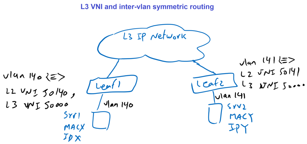
In the topology, we have a VXLAN network with two leaf switches. Server1 with MACX and IPX is connected to leaf1 and it is configured in VLAN 140. VLAN 140 is mapped to VNI 50140 in leaf1. Another server with MACY and IPY is connected to leaf2 and it is in VLAN 141. VLAN 141 is mapped to VNI 50141. These two server in different VLAN want to communicate to each other. So in this topology we want to see how inter vlan routing works in VXLAN network.
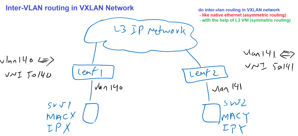
at first, I want to do inter vlan routing on a VXLAN network like a native ethernet network. However, it is not what has actually been implemented and supported by cisco devices. this method is called asymmetric routing. In the second method, we will do inter vlan routing with the help of L3 VNI what has actually been implemented and supported by cisco devices. the second method is called symmetric routing which has actually been implemented and supported by cisco devices.
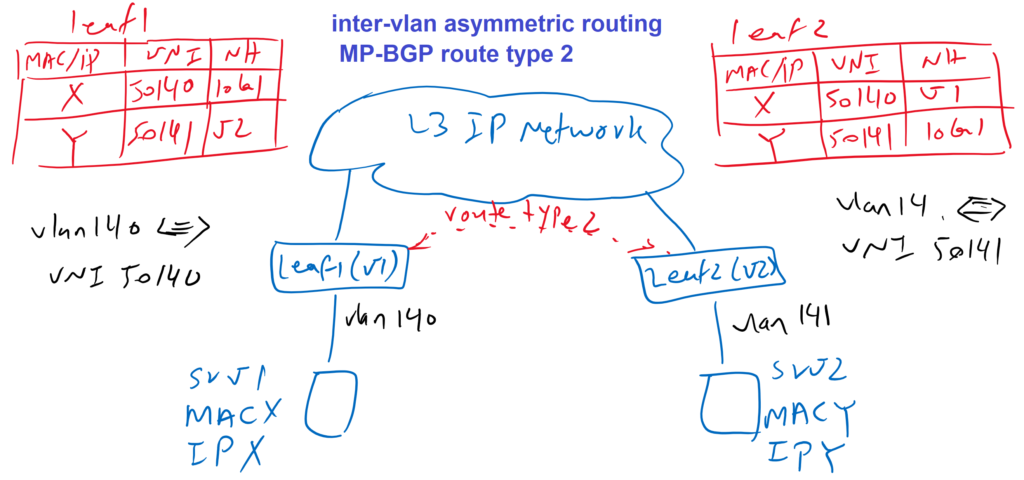
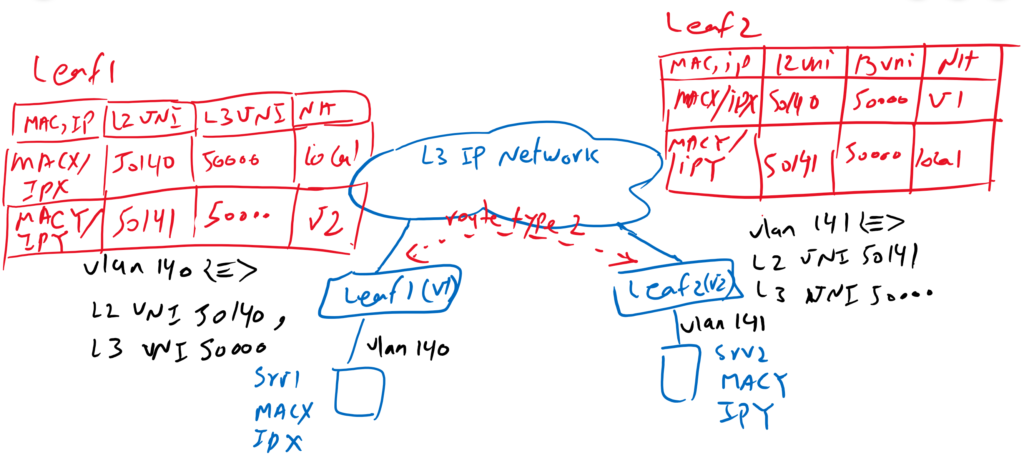
As you know, MAC and IP Addresses are advertised and learned through MP-BGP EVPN route type 2. So leaf1 and leaf2 switches knows exactly where each server is located in the network. For example leaf1 knows that MACY/IPY with L2 VNI 50141 is behind leaf2 switch with VTEP address V2. Notice that L3 VNI is not show here, because inter vlan routing with asymmetric method, does not need L3 VNI to forward traffic. However in reality, L3 VNI is also advertised and we will learn inte vlan routing with L3 VNI in the next method.
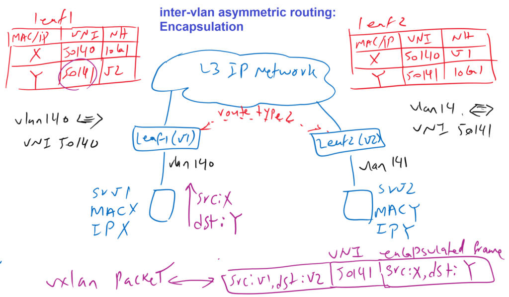
If we now assume that serverver1 with source IPX sends traffic to Server2 with destination IPY, the traffic will be forwarded to the anycast gateway of server1, which is located in the Leaf1 switch. Leaf1 search it’s forwarding table and it knows that Y is in different VNI and behind leaf2 switch with V2 as VTEP address. So the original packet which is in VNI 50140 is encapsulated in VNI 50141 and with source V1, VTEP address of leaf1 and destination V2, VTEP address of leaf2. So the traffic from VNI 50140 is routed to VNI 50141, as it is in native ethernet network.
Reverse traffic from VLAN 141, with source Y and destination X, is routed in leaf2 from VNI 50141 to VNI 50140. So the reverse traffic will be forwarded in VNI 50140 in VXLAN network.
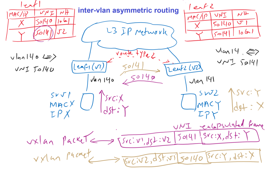
As you can see, sent traffic is forwarded with VNI 50141 and reverse traffic with VNI 50140 on the VXLAN network. So sent and reverse traffic can be routed on different paths, which is not good in a network environment. Since many services like firewall are not so easy to configure with asymmetric traffic.
VXLAN Symmetric Routing
Assume the same topology again, but this time L3-VNI is also configured in leaf switches. L3-VNI is configured per Tenant. This means that all VLANs or VNIs in the same VRF have an identical L3-VNI that is used for inter-vlan routing. L3 VNI 50000 is configured in the tenant here.
In the MP-BGP EVPN route type 2, L3-VNI is also advertised in addition to L2VNI. Switch Leaf1 knows, for example, that destination Y can be reached via Leaf2 with the VTEP address V2, with L2 VNI 50141 and L3 VNI 50000. When a switch receive a traffic which destination is in another VNI, traffic is forwarded through L3 VNI.
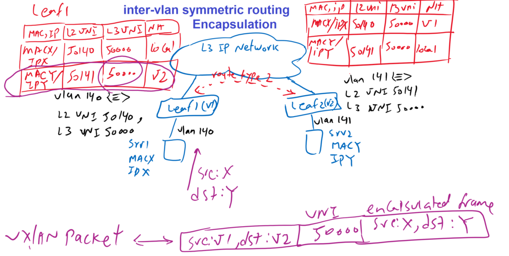
In our topology, server1 sends traffic with source X and destination Y. Leaf1 receives the traffic in VLAN 140 or L2 VNI 50140, but the destination is in L2 VNI 50141. Leaf1 therefore encapsulates the original packet in L3 VNI or VNI 50000 with source V1 and destination V2. So inter vlan traffic is forwarded in VXLAN network in L3 VNI which is 50000 here.
Reverse traffic is also forwarded in L3 VNI 50000 since source is in L2 VNI 50141 but the destination is in L2 VNI 50140. So leaf2 switch forward the traffic in L3 VNI which is 50000 in out Tenant.
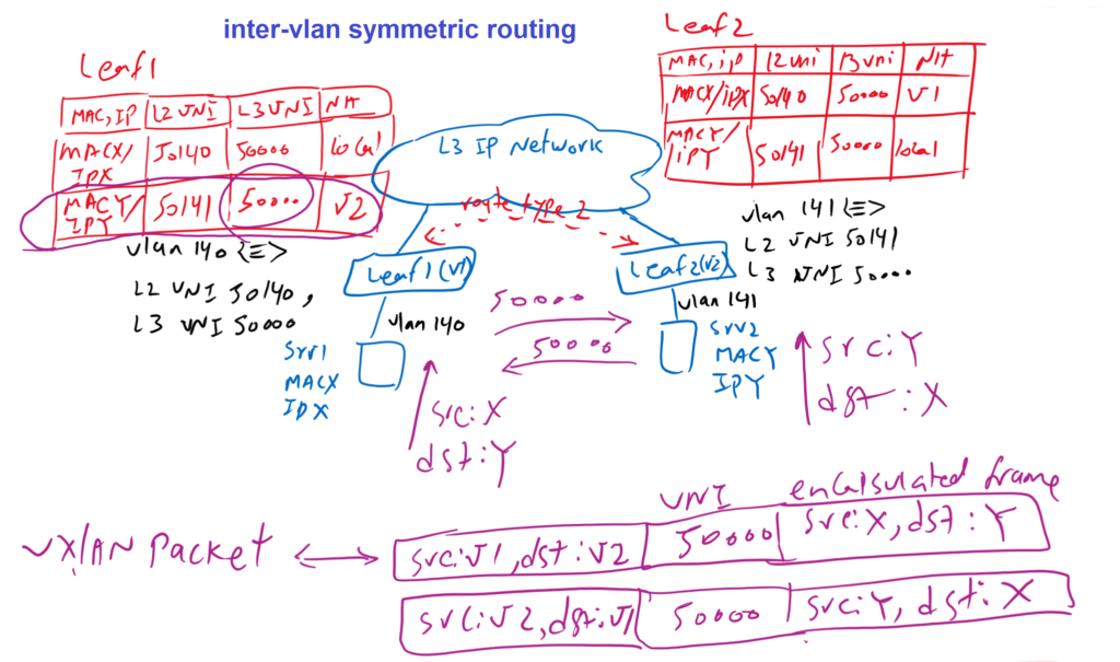
In summary, all inter-Vlan routing traffic is always forwarded in L3-VNI. This method is also known as symmetric routing and what is actually implemented and it is supported by cisco devices.
Thanks for making all clear.
after countless videos and hours of searching, i finally found something simple and logical to explain to me the concept of vxlan in a simple and easy way..one word-THANK YOU