VXLAN vPC Concept
With vPC technology, two leaf switches that are connected to servers, customer switches or routers behave like one switch. so each device that is connected to two leaf switches, assume that it is connected to one switch and can create a port-channel. therefore a connection error or failure of a leaf switch does not interrupt the network traffic.
I am not going to talk about the details of vPC technology and I assume that you are already familiar with this technology. But we will talk about what will be different for vPC on the VXLAN network.
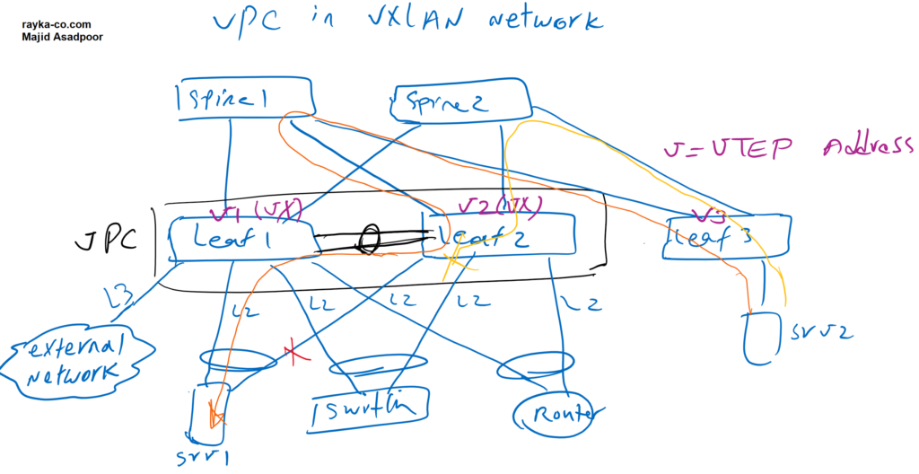
The first difference is the configuration of the VTEP address. Usually there is a VTEP address in each switch, which acts as the VXLAN tunnel termination address. If we configure two switches as a VPC domain, they must have a VTEP virtual address that is shared by both leaf switches. The VTEP virtual IP address is the VXLAN next-hop address advertised to other leaf switches. In other words any Route Type 2 which advertise MAC and IP addresses behind leaf1 and leaf2 switches, will be advertised with VTEP-VIP as next-hop. This also applies to Route Type 5 which advertise external prefixes.
In our topology, V1, V2 and V3 are the VTEP addresses of the Leaf1, Leaf2 and Leaf3 switches. When we configure Leaf1 and Leaf2 switches in one VPC domain, Vx will be VTEP Virtual IP address of both Leaf1 and Leaf2 switches, which is configured as the secondary IP address in the loopback interface. Vx will be next-hop address in other leaf switches to reach MAC and IP addresses and also external prefixes behind leaf1 and leaf2 switches.
Now suppose a device is connected to only one of two leaf switches participating in the VPC, or it is connected to both leaf switches but one link is broken. What happens if incoming traffic reaches the switch that has no connection to the end device?
If the link is an L2 link in leaf switches, it behaves like any orphaned device. The data traffic belonging to orphaned devices may be forwarded to the end devices through peer link. In our topology, the Server1 connection to the Leaf2 switch is broken. Incoming traffic from Server2 may reach the Leaf2 switch, since both leaf switches have the same VTEP virtual IP. Incoming traffic is forwarded over the peer-link to reach server1 as we have shown with orange color.
When the link is a L3 link, like when we connect to an external network through just one of the leaf switches, Incoming traffic is expected to always reach the correct leaf switch, otherwise the traffic will be dropped since the routing information is missed in another leaf switch for external prefixes.
As we have shown here with yellow color, the traffic from Server2 to the external network is forwarded to the VTEP virtual IP, but it reaches the Leaf2 switch, which has no connection to the external network. Traffic is then discarded because Leaf2-Switch has no routing information for external prefixes.
To fix this Problem, we can add a command that force leaf1 switch to advertise external prefixes with VTEP primary address as next-hop address instead of VTEP virtual IP. External prefixes are advertised through Route Type 5 in L2VPN EVPN address-family in BGP. We can force that Route Type 5 are advertised with VTEP primary address also called physical Address (PIP) as next-hop address.
VXLAN vPC Topology Example
This is the topology through which I implemented vPC on the VXLAN network. this is exact topology that we have used in our first VXLAN EVPN configuration Example. The difference is that leaf1 and leaf2 switch participate in one VPC domain. Interface Ethernet 1/5 is added in Port-channel1 and used as peer-link.
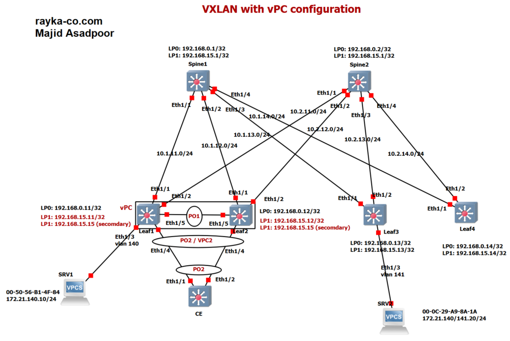
In this topology, the CE switch is connected to both the Leaf1 and Leaf2 switches. As you can see, CE assumes that both uplinks are connected to one switch, so that both uplinks are aggregated into one logical port-channel-2 interface.
In the Leaf1 and Leaf2 switches, Eth1/4 interfaces that are connected to the CE switch are aggregated as a Virtual Port Channel Interface, VPC2.
VPC on the VXLAN network does not come up until you configure a virtual VTEP address. We have configured virtual VTEP address as a secondary address in the Loopback1 interface. The primary address of the Loopback interface in the Leaf1 and Leaf2 switches are 192.168.15.11 and 192.168.15.12, but 192.168.15.15 is configured in both leaf switches as the secondary IP address that is used as the virtual VTEP address.
VXLAN vPC Configuration
I’ve divided the configuration into three parts. Before any configuration, make sure that you have configured the VXLAN network exactly as VXLAN configuration example1.
9. VXLAN EVPN Configuration Example1 Part1
VXLAN vPC Configuration Reference
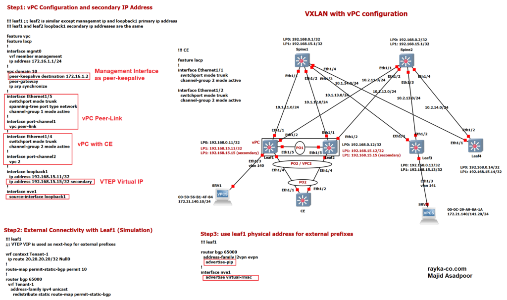
In the first step I have configured VPC between leaf1 and leaf2 switch. I will not discuss the details of VPC since I assume that you are familiar with this technology. I have configured Interface Eth1/5 into Portchannel1 and then used Port-channle1 as Peer-link. I have Configured Virtual Port-Channel 2 with CE switch. Difference is that VPC does not come up until you configure the same secondary IP address in both leaf1 and leaf2 switch as VTEP virtual IP Address.
!!! leaf1 ;;; leaf2 is similar except managemnt ip and loopback1 primary ip address
!!! leaf1 and leaf2 loopback1 secondary ip addresses are the same

feature vpc
feature lacp
!
interface mgmt0
  vrf member management
  ip address 172.16.1.1/24
!
vpc domain 10
  peer-keepalive destination 172.16.1.2
  peer-gateway
  ip arp synchronize
!
interface Ethernet1/5
  switchport mode trunk
  spanning-tree port type network
  channel-group 1 mode active
!
interface port-channel1
  vpc peer-link
!
interface Ethernet1/4
  switchport mode trunk
  channel-group 2 mode active
!
interface port-channel2
  vpc 2
!
interface loopback1
  ip address 192.168.15.11/32
  ip address 192.168.15.15/32 secondary
!
interface nve1
  source-interface loopback1
!!! CE
interface Ethernet1/1
switchport mode trunk
channel-group 2 mode active
interface Ethernet1/2
switchport mode trunk
channel-group 2 mode activeUse the “show VPC” command to ensure that VPC and Virtual Port-Channel2 are UP. As you can see, the VPC is success and the Leaf1 switch is the primary switch in the VPC. VPC Keep-Alive, VPC Peer-Link and also VPC 2, which is connected to CE Switch, is also UP.
leaf1(config-if-nve)# show vpc
Legend:
                (*) - local vPC is down, forwarding via vPC peer-link

vPC domain id                     : 10
Peer status                       : peer adjacency formed ok
vPC keep-alive status             : peer is alive
Configuration consistency status  : success
Per-vlan consistency status       : success
Type-2 consistency status         : success
vPC role                          : primary
Number of vPCs configured         : 1
Peer Gateway                      : Enabled
Dual-active excluded VLANs        : -
Graceful Consistency Check        : Enabled
Auto-recovery status              : Disabled
Delay-restore status              : Timer is off.(timeout = 30s)
Delay-restore SVI status          : Timer is off.(timeout = 10s)
Operational Layer3 Peer-router    : Disabled
Virtual-peerlink mode             : Disabled

vPC Peer-link status
---------------------------------------------------------------------
id    Port   Status Active vlans
--    ----   ------ -------------------------------------------------
1     Po1    up     1,140-141,999


vPC status
----------------------------------------------------------------------------
Id    Port          Status Consistency Reason                Active vlans
--    ------------  ------ ----------- ------                ---------------
2     Po2           up     success     success               1,140-141,999
!!! CE
CE(config-if)# show port-channel summary
Flags: D - Down P - Up in port-channel (members)
I - Individual H - Hot-standby (LACP only)
s - Suspended r - Module-removed
b - BFD Session Wait
S - Switched R - Routed
U - Up (port-channel)
p - Up in delay-lacp mode (member)
M - Not in use. Min-links not met
--------------------------------------------------------------------------------
Group Port- Type Protocol Member Ports
Channel
--------------------------------------------------------------------------------
2 Po2(SU) Eth LACP Eth1/1(P) Eth1/2(P)
In the second step, an external network is simulated in leaf1 switch. A static route for destination 20.20.20.20 is advertised in BGP L2VPN EVPN address-family.
!!! leaf1
;;; VTEP VIP is used as next-hop for external prefixes

vrf context Tenant-1
  ip route 20.20.20.20/32 Null0
!
route-map permit-static-bgp permit 10
!
router bgp 65000
  vrf Tenant-1
    address-family ipv4 unicast
      redistribute static route-map permit-static-bgp
With command “show bgp l2vpn evpn ” in leaf3 switch, you can make sure that both Route Type 2 and Route Type 5 are advertised with VTEP virtual IP, 192.168.15.15, as next-hop address.
leaf3(config)# show bgp l2vpn evpn
BGP routing table information for VRF default, address family L2VPN EVPN
BGP table version is 3292, Local Router ID is 192.168.0.13
Status: s-suppressed, x-deleted, S-stale, d-dampened, h-history, *-valid, >-best
Path type: i-internal, e-external, c-confed, l-local, a-aggregate, r-redist, I-i
njected
Origin codes: i - IGP, e - EGP, ? - incomplete, | - multipath, & - backup, 2 - b
est2

   Network            Next Hop            Metric     LocPrf     Weight Path
Route Distinguisher: 192.168.0.11:3
* i[5]:[0]:[0]:[32]:[20.20.20.20]/224
                      192.168.15.15            0        100          0 ?
*>i                   192.168.15.15            0        100          0 ?

Route Distinguisher: 192.168.0.11:32907    (L2VNI 50140)
x i[2]:[0]:[0]:[48]:[0050.56b1.4f84]:[32]:[172.21.140.10]/272
                      192.168.15.15                     100          0 i
x i                   192.168.15.15                     100          0 i
*>i                   192.168.15.15                     100          0 i
* i                   192.168.15.15                     100          0 i

Route Distinguisher: 192.168.0.11:32908    (L2VNI 50141)
*>l[2]:[0]:[0]:[48]:[000c.29a9.8a1a]:[0]:[0.0.0.0]/216
                      192.168.15.13                     100      32768 i
*>l[2]:[0]:[0]:[48]:[000c.29a9.8a1a]:[32]:[172.21.141.20]/272
                      192.168.15.13                     100      32768 i

Route Distinguisher: 192.168.0.12:32907
x i[2]:[0]:[0]:[48]:[0050.56b1.4f84]:[32]:[172.21.140.10]/248
                      192.168.15.15                     100          0 i
x i                   192.168.15.15                     100          0 i
leaf3(config)# show l2route mac-ip all
Flags -(Rmac):Router MAC (Stt):Static (L):Local (R):Remote (V):vPC link
(Dup):Duplicate (Spl):Split (Rcv):Recv(D):Del Pending (S):Stale (C):Clear
(Ps):Peer Sync (Ro):Re-Originated (Orp):Orphan
Topology Mac Address Host IP Prod Flags Seq No Next-
Hops
----------- -------------- --------------- ------ ---------- ---------------
140 0050.56b1.4f84 172.21.140.10 BGP -- 0 192.168.15.15
141 000c.29a9.8a1a 172.21.141.20 HMM -- 0 Local
But as you know, this creates problems for external prefixes when the reverse traffic reaches the Leaf2 switch which has no route information for external prefixes.
To fix this problem, we added two commands in step 3 that advertise the physical or primary IP address of the Loopback1 interface as the VXLAN next hop address for Route Type 5 prefixes to other leaf switches. Command “advertise-pip” in BGP L2VPN EVPN address-family and command “advertise virtual-rmac” in interface nve context mode together fix this problem.
!!! leaf1
router bgp 65000
  address-family l2vpn evpn
    advertise-pip
!
interface nve1
    advertise virtual-rmac
Remember, these two commands have no effect on Route Type 2. Route Type 2 is still advertised with the virtual VTEP IP as the address of the next-hop to other leaf switches. These two commands only affect the Route Type 5 advertisement.
With command “show bgp l2vpn evpn ” in leaf3 switch, you can make sure what has changed after adding these two commands.
leaf3(config)# show bgp l2vpn evpn
BGP routing table information for VRF default, address family L2VPN EVPN
BGP table version is 3265, Local Router ID is 192.168.0.13
Status: s-suppressed, x-deleted, S-stale, d-dampened, h-history, *-valid, >-best
Path type: i-internal, e-external, c-confed, l-local, a-aggregate, r-redist, I-i
njected
Origin codes: i - IGP, e - EGP, ? - incomplete, | - multipath, & - backup, 2 - b
est2

   Network            Next Hop            Metric     LocPrf     Weight Path
Route Distinguisher: 192.168.0.11:3
*>i[2]:[0]:[0]:[48]:[000c.296e.62c9]:[0]:[0.0.0.0]/216
                      192.168.15.15                     100          0 i
* i                   192.168.15.15                     100          0 i
* i[5]:[0]:[0]:[32]:[20.20.20.20]/224
                      192.168.15.11            0        100          0 ?
*>i                   192.168.15.11            0        100          0 ?

Route Distinguisher: 192.168.0.11:32907    (L2VNI 50140)
*>i[2]:[0]:[0]:[48]:[0050.56b1.4f84]:[0]:[0.0.0.0]/216
                      192.168.15.15                     100          0 i
* i                   192.168.15.15                     100          0 i
*>i[2]:[0]:[0]:[48]:[0050.56b1.4f84]:[32]:[172.21.140.10]/272
                      192.168.15.15                     100          0 i
* i                   192.168.15.15                     100          0 i
* i                   192.168.15.15                     100          0 i

Route Distinguisher: 192.168.0.11:32908    (L2VNI 50141)
*>l[2]:[0]:[0]:[48]:[000c.29a9.8a1a]:[0]:[0.0.0.0]/216
                      192.168.15.13                     100      32768 i
*>l[2]:[0]:[0]:[48]:[000c.29a9.8a1a]:[32]:[172.21.141.20]/272
                      192.168.15.13                     100      32768 i

Route Distinguisher: 192.168.0.12:3
*>i[2]:[0]:[0]:[48]:[000c.29d6.80d2]:[0]:[0.0.0.0]/216
                      192.168.15.15                     100          0 i
* i                   192.168.15.15                     100          0 i

Route Distinguisher: 192.168.0.12:32907
*>i[2]:[0]:[0]:[48]:[0050.56b1.4f84]:[32]:[172.21.140.10]/272
                      192.168.15.15                     100          0 i
* i                   192.168.15.15                     100          0 i
Majid jaan; it is very nicely done, but I wish you had the vpc included.
Hi Fereidoun
Thank you
seperate training for vPC will be created
Hi Majid,
Content is very good to understand the traditional vPC in VxLAN.
Please post the content/video for vPC fabric peering with VxLAN setup