VXLAN EVPN COnfiguration Example1 based on cisco dcloud scenario
VXLAN EVPN Configuration Example1 Topology Description
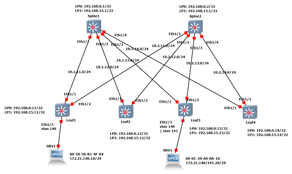
This is our topology with two spine switches and four leaf switches. All leaf and spine switches are interconnected. There is no connection between the leaf switches. There is also no connection between the spine switches.
VXAN EVPN leaf and spine architecture
Interface numbers are displayed in the topology. The interfaces Eth1/1 to Eth1/4 in the Spine1 switch are connected to Eth1/1 of the Leaf1 to Leaf4 switches. The interfaces Eth1/1 to Eth1/4 in the Spine2 switch are connected to Eth1/2 of the Leaf1 to Leaf4 switches.
IP addresses of the links and loopback interfaces are configured using the device number. Number 1 and number 2 are taken into account for Spine1 and Spine2 switches. Numbers 11 to Number 14 apply to switches Leaf1 to Leaf4.
Therefore the IP address of the connection between spine1 and leaf1 is 10.1.11.x for example. the last digit is also the device number. For example, 10.1.11.11/24 is the IP address of Leaf1 that is connected to Spine1 Switch. It is recommended to use IP unnumbered for addressing point-to-point interfaces, if your switch supports it.
We have two loopback interfaces in each device. Loopback0 interface with the IP address 192.168.0.x, which is used for the OSPF router ID and the iBGP neighborship. The loopback 1 interface with the IP address 192.168.15.x is used in leaf switches as the VTEP address for the VXLAN tunnel termination. The loopback 1 interface in spine switches is used for anycast RP in PIM multicast routing. Note that the IP address of the Loopback 1 interface is the same in Spine1 and Spine2 switches as it is used as the anycast IP for RP.
VXLAN EVPN Configuration Example1 Properties
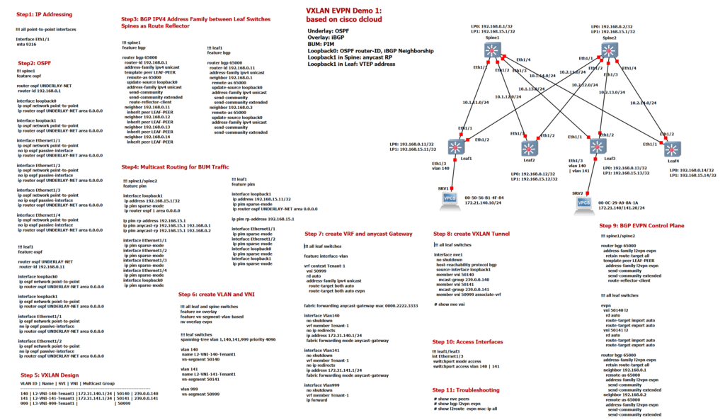
In the first demo we are using OSPF as the underlay IGP protocol. iBGP is used as an overlay protocol that advertises MAC and IP addresses of endpoints connected to leaf switches between leaf switches. Spine switches are used as router reflectors in iBGP. In the next demo we will be using eBGP as the overlay routing protocol.
For the forwarding of BUM data traffic, we implement PIM multicast routing in this demonstration. Spine switches are used as PIM anycast RP. In the next demonstration, we will not implement PIM multicast routing instead we’ll use the unicast replication method which is another method for forwarding BUM Traffic.
VXLAN EVPN Configuration Example1 Steps
I have divided the VXLAN EVPN implementation into 11 steps that we will discuss in order.
VXLAN EVPN Configuration Example1 Step1
The first step is IP addressing of the infrastructure and enabling MTU for forwarding Jumbo frames. I didn’t show IP Addressing configuration here, but IP addresses are displayed in the topology. As I have said, The best solution is to use IP unnumbered in point-to-point interfaces so that a minimal IP addresses are used with the condition that your switches support it.
VXLAN adds 50 bytes to the original Ethernet frame. To avoid fragmentation, we have to adjust the MTU in point-to-point connections. Datacenters often require Jumbo MTU because most server NICs support up to 9000 byte frames to be sent. Using an MTU of 9216 bytes allows for the VXLAN overhead plus the maximum server MTU.
interface Eth1/1
 mtu 9216
VXLAN EVPN Configuration Example1 Step2
The second step is to implement OSPF as the underlay protocol. Network type Point-to-Point is activated in all links to ignore the DR/BDR selection. To make sure that your OSPF configuration works correctly, you can ping between loopback interface.
!!! spine1
feature ospf

router ospf UNDERLAY-NET
 router-id 192.168.0.1

interface loopback1
 ip ospf network point-to-point
 ip router ospf UNDERLAY-NET area 0.0.0.0

interface Ethernet1/1
 ip ospf network point-to-point
 no ip ospf passive-interface
 ip router ospf UNDERLAY-NET area 0.0.0.0

interface Ethernet1/2
 ip ospf network point-to-point
 no ip ospf passive-interface
 ip router ospf UNDERLAY-NET area 0.0.0.0

interface Ethernet1/3
 ip ospf network point-to-point
 no ip ospf passive-interface
 ip router ospf UNDERLAY-NET area 0.0.0.0

interface Ethernet1/4
 ip ospf network point-to-point
 no ip ospf passive-interface
 ip router ospf UNDERLAY-NET area 0.0.0.0

!!! leaf1
feature ospf

router ospf UNDERLAY-NET
 router-id 192.168.0.11

interface loopback0
 ip ospf network point-to-point

interface Ethernet1/1
 ip ospf network point-to-point
 no ip ospf passive-interface
 ip router ospf UNDERLAY-NET area 0.0.0.0

interface Ethernet1/2
 ip ospf network point-to-point
 no ip ospf passive-interface
 ip router ospf UNDERLAY-NET area 0.0.0.0
VXLAN EVPN Configuration Example1 Step3
In the third step we use iBGP between leaf switches with the help of route reflectors implemented in spine switches. In this step, only the IPv4 address family is implemented in iBGP. The EVPN address family is implemented in the next few steps. In spine switches, all leaf switches from 192.168.0.11 to 192.168.0.14 are configured as route reflector clients. In all leaf switches, 192.168.0.1 and 192.168.0.2 are configured as iBGP neighbours, which are route reflectors.
!!! spine1
feature bgp

router bgp 65000
  router-id 192.168.0.1
  address-family ipv4 unicast
  template peer LEAF-PEER
    remote-as 65000
    update-source loopback0
    address-family ipv4 unicast
      send-community
      send-community extended
      route-reflector-client
  neighbor 192.168.0.11
    inherit peer LEAF-PEER
  neighbor 192.168.0.12
    inherit peer LEAF-PEER
  neighbor 192.168.0.13
    inherit peer LEAF-PEER
  neighbor 192.168.0.14
    inherit peer LEAF-PEER


!!! leaf1
feature bgp

router bgp 65000
  router-id 192.168.0.11
  address-family ipv4 unicast
  neighbor 192.168.0.1
    remote-as 65000
    update-source loopback0
    address-family ipv4 unicast
      send-community
      send-community extended
  neighbor 192.168.0.2
    remote-as 65000
    update-source loopback0
    address-family ipv4 unicast
      send-community
      send-community extended
To ensure that iBGP is working correctly, you can use “show ip bgp summary” in spine and leaf switches. If there is nothing in the status column, it means that iBGP has been set up correctly.
spine1# show ip bgp summary
BGP summary information for VRF default, address family IPv4 Unicast
BGP router identifier 192.168.0.1, local AS number 65000
BGP table version is 3, IPv4 Unicast config peers 4, capable peers 4
0 network entries and 0 paths using 0 bytes of memory
BGP attribute entries [0/0], BGP AS path entries [0/0]
BGP community entries [0/0], BGP clusterlist entries [0/0]

Neighbor        V    AS MsgRcvd MsgSent   TblVer  InQ OutQ Up/Down  State/PfxRcd
192.168.0.11    4 65000    2306    1999        3    0    0    1d04h 0
192.168.0.12    4 65000    1691    2184        3    0    0    1d04h 0
192.168.0.13    4 65000    2316    1992        3    0    0    1d04h 0
192.168.0.14    4 65000    1690    2182        3    0    0    1d04h 0

leaf1# show ip bgp summary
BGP summary information for VRF default, address family IPv4 Unicast
BGP router identifier 192.168.0.11, local AS number 65000
BGP table version is 3, IPv4 Unicast config peers 2, capable peers 2
0 network entries and 0 paths using 0 bytes of memory
BGP attribute entries [0/0], BGP AS path entries [0/0]
BGP community entries [0/0], BGP clusterlist entries [2/8]

Neighbor        V    AS MsgRcvd MsgSent   TblVer  InQ OutQ Up/Down  State/PfxRcd
192.168.0.1     4 65000    2319    1994        3    0    0    1d04h 0
192.168.0.2     4 65000    2319    1993        3    0    0    1d04h 0
VXLAN EVPN Configuration Example1 Step4
In Step 4, PIM multicast routing with anycast RP in spine switches is implemented. PIM sparse-mode is enabled in all interfaces including loopback0 and loopabck1 interfaces. Note that the IP address of the Loopback 1 interface is the same in Spine1 and Spine2 switches as it is used as the anycast IP for RP. RP is manually configured as anycast RP which the configuration is shown here.
!!! spine1/spine2
feature pim

interface loopback1
 ip address 192.168.15.1/32
 ip pim sparse-mode
 ip router ospf 1 area 0.0.0.0

ip pim rp-address 192.168.15.1
ip pim anycast-rp 192.168.15.1 192.168.0.1
ip pim anycast-rp 192.168.15.1 192.168.0.2

interface Ethernet1/1
 ip pim sparse-mode
interface Ethernet1/2
 ip pim sparse-mode
interface Ethernet1/3
 ip pim sparse-mode
interface Ethernet1/4
 ip pim sparse-mode
interface loopback0
 ip pim sparse-mode

!!! leaf1
feature pim

interface loopback1
 ip address 192.168.15.11/32
 ip pim sparse-mode
 ip router ospf UNDERLAY-NET area 0.0.0.0

ip pim rp-address 192.168.15.1

interface Ethernet1/1
 ip pim sparse-mode
interface Ethernet1/2
 ip pim sparse-mode
interface loopback0
 ip pim sparse-mode
interface loopback1
 ip pim sparse-mode
You can use the “show ip pim neighbor” command in leaf and spine switches to make sure that it is working properly.
spine1# show ip pim neighbor
PIM Neighbor Status for VRF "default"
Neighbor        Interface            Uptime    Expires   DR       Bidir-  BFD
 ECMP Redirect
                                                         Priority Capable State
    Capable
10.1.11.11      Ethernet1/1          1d04h     00:01:18  1        yes     n/a
  no
10.1.12.12      Ethernet1/2          1d04h     00:01:22  1        yes     n/a
  no
10.1.13.13      Ethernet1/3          1d04h     00:01:37  1        yes     n/a
  no
10.1.14.14      Ethernet1/4          1d04h     00:01:39  1        yes     n/a
  no


leaf1# show ip pim neighbor
PIM Neighbor Status for VRF "default"
Neighbor        Interface            Uptime    Expires   DR       Bidir-  BFD
 ECMP Redirect
                                                         Priority Capable State
    Capable
10.1.11.1       Ethernet1/1          1d04h     00:01:36  1        yes     n/a
  no
10.2.11.2       Ethernet1/2          1d04h     00:01:25  1        yes     n/a
  no
VXLAN EVPN Configuration Example1 Step5
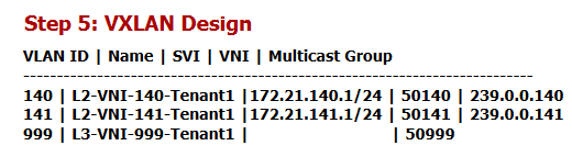
Step 5 shows the design of our VXLAN EVPN demo. As you can see, we have two VLAN 140 and VLAN 141 mapped in leaf switches on VNI 50140 and VNI 50141. VLAN 999 is mapped to L3 VNI 50999, which is used for the VXLAN routing that we discussed theoretically in the previous sections. for each L2 VNI a specific multicast address is used to handle the BUM traffic. 239.0.0.140 for L2 VNI 50140 and 239.0.0.141 for L2 VNI 50141. The anycast gateway’s IP addresses for VLAN 140 and VLAN 141 are also 172.21.140.1 and 172.21.141.1 which the same address will be configured in all leaf switches.
We’ll end our discussion here and we’ll move on to the next section to avoid making the video too long.