Cisco SD-WAN Service VPN are subnets and services distributed behind SD-WAN network which communicate over SD-WAN infrastructure. in other words, the LAN part of SD-WAN infrastructure that is not yet ready in our topology. This section is devoted to create LAN section of the SD-WAN infrastructure using Service VPN.
SD-WAN Service VPN Concept
Just to review, we have already configured SD-WAN controllers and WAN Edge routers over internet transport. we have changed the configuration mode from CLI to vManage. Then we have added the second transport, MPLS. there is just one step to complete our SD-WAN infrastructure.
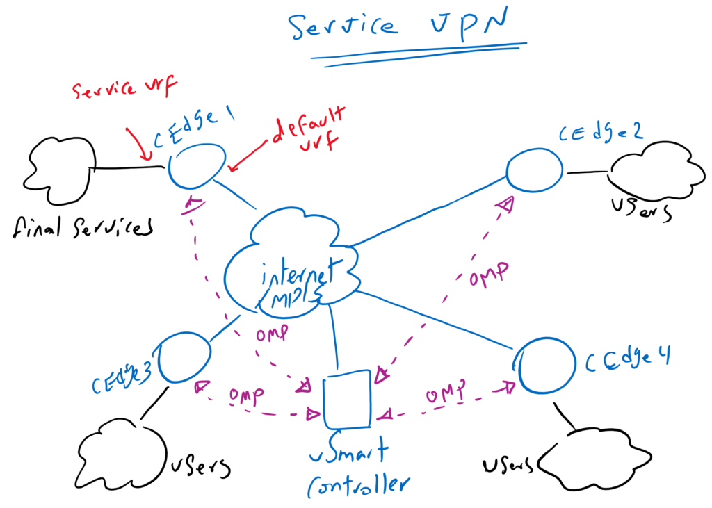
We have not still configured the LAN section of SD-WAN infrastructure which host real service and also users who use these services. This is done through Service VPN in cisco SD-WAN Architecture.
This is called Service VPN because they are configured in a different VRF as the default VRF to which interfaces connected to WAN transports are assigned.
Subnets in Service VPN are advertised between WAN edge routers via OMP routing protocol and with the help of the vSmart controller. OMP routing protocol will be discussed in the next section.
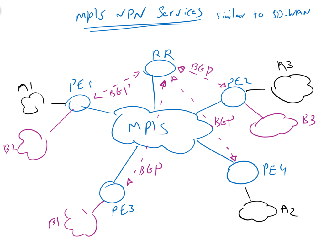
If you are familiar with MPLS VPN Service, Service VPN in SD-WAN infrastructure is similar to VPN Services in MPLS network. in MPLS, VPN Services are advertised through BGP protocol between PE routers. in SD-WAN, OMP routing protocol is used. In MPLS, Services are connected to PE routers. in SD-WAN, Services are connected to WAN Edge routers. in MPLS, route reflector is used to advertise BGP routes between PE routers. in SD-WAN, vSmart is has the role of route reflector.
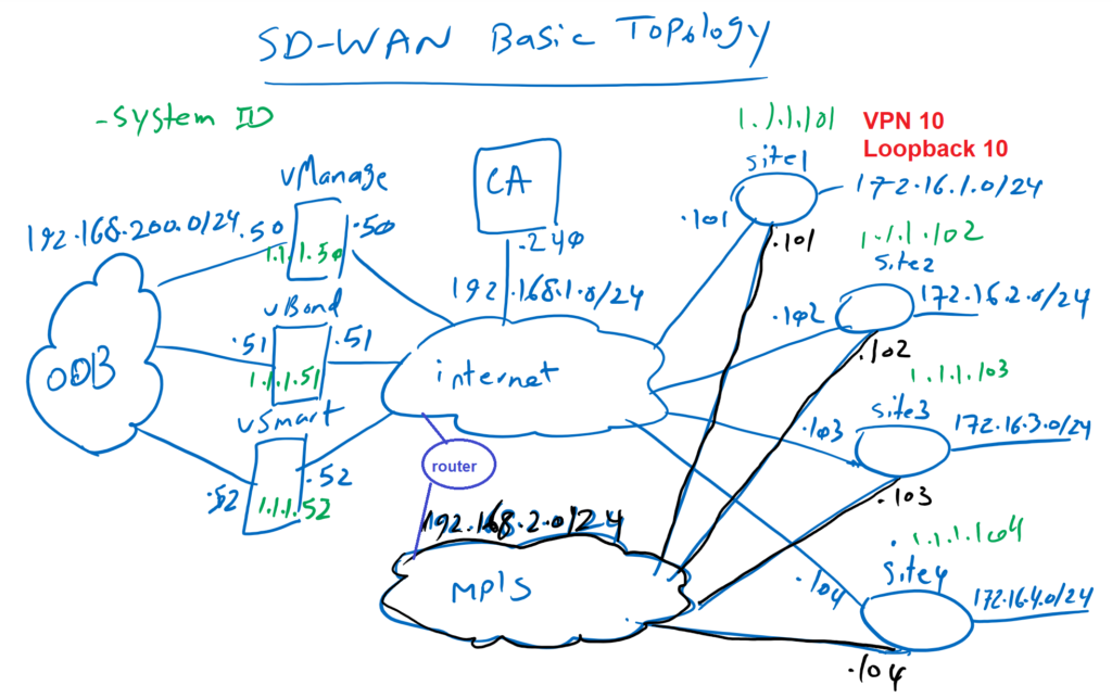
We will simulate LAN section of SD-WAN infrastructure with loopback interfaces. We will create a new VPN in addition to VPN 0 and VPN 512 for the purpose of Service VPN, here VPN 10. Then we will assign loopback interfaces to this new VPN service, here loopback10 interface.
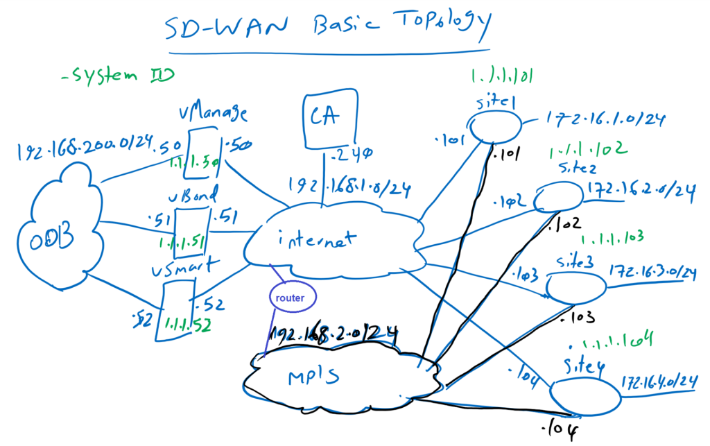
IP address of interfaces belonging to the new VPN service is in the range of 172.16.1.0/24 in site1 to 172.16.4.0/24 in site4.
These two steps, adding new VPN service and adding loopback interface inside VPN service, is what will be done in this section to complete SD-WAN infrastructure.
The Configuration will be sone through SD-WAN template because the configuration mode of the SD-WAN infrastructure has already been changed from CLI to vManage.
Service VPN routing concept, is discussed in the next section. This section is only intended to complete our SD-WAN infrastructure by adding Service VPN.
Add Service VPN using SD-WAN Templates
Let’s implement Service VPN with adding required feature template.
device type: csr1000v
Template: Cisco VPN
Template Name: CSR1000v_VPN10
Description: CSR1000v_VPN10
Section: Basic Configuration
Another feature template must be added for the LAN interface of WAN Edge routers within Service VPN, which is simulated here with the loopback10 interface.
device type: csr1000v
Template: Cisco VPN Interface Ethernet
Template Name: CSR1000v_Interface_LAN
Description: CSR1000v_Interface_LAN
Section: Basic Configuration
Now these two new feature templated must be added into existing device templated attached to WAN routers.
Template Name: CSR1000v_Device_Template
Description: CSR1000v_Device_Template
Section: Service VPN
In this step you will be asked to enter the value of the device-specific parameters. IP address of loopback10 interface must be configured, based on the topology.
When applying the configuration, it can be seen that a new VRF is created with RD and RT values like what we do in MPLS VPN Services and also Loopback 10 interface is assigned to this new VRF.


In this section, we have completed our SD-WAN infrastructure. from now on we can work on real WAN requirements like topology, security and QoS configurations.


