Adding a second transport in SD-WAN is what we will implement in this section. We have already set up an SD-WAN infrastructure via internet transport. In this section, our second transport, MPLS, will be added to our SD-WAN infrastructure. This is done through the vManage GUI interface since we have already changed the configuration modes from CLI to vManage.
SD-WAN Basic Topology
Before starting , let’s review our topology once again. Our WAN Edge routers are connected to each other through two transport, Internet, with address range 192.168.1.0/24 and MPLS, with address range 192.168.2.0/24. Controllers are also connected in internet transport.
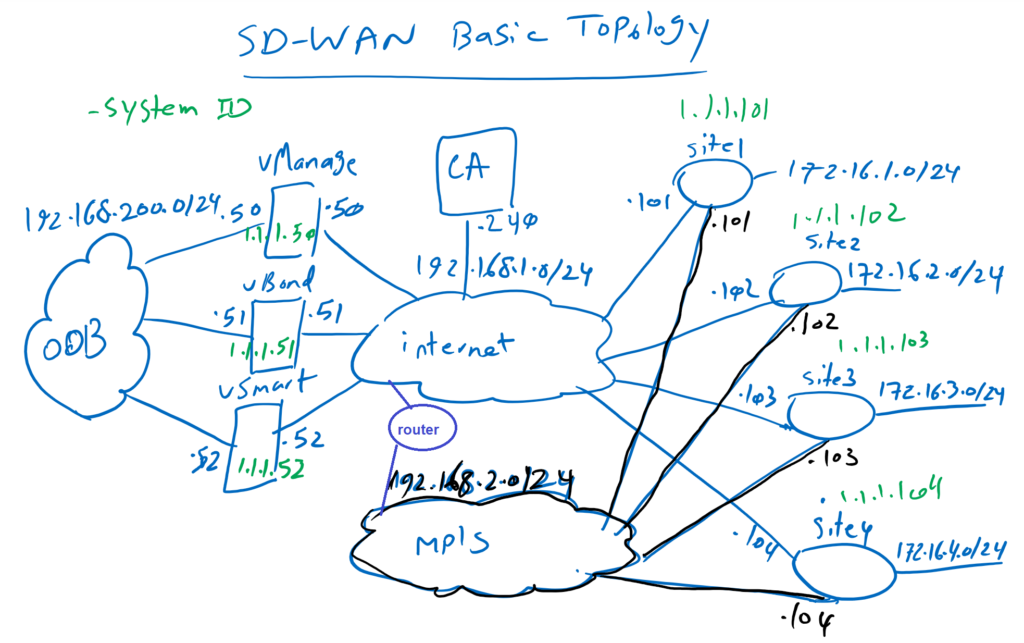
There is already one default route through internet transport but there is no route over MPLS transport which must be added in this section.
Add Second Transport in VPN0
Two steps must be configured to add second MPLS transport. First, the second interface in WAN edge routers connected to MPLS transport in VPN0 must be enabled and configured and second, routing information must be provided also in second transport so that WAN edge routers can establish a DTLS connection with controllers through MPLS transport. here in our topology, this is done thourgh a router which is connected to both transports.
with feature Template, Cisco VPN Interface Ethernet, the second interface connected to MPLS transport can be configured like what it is already configured for interface connected to Internet transport.
device type: CSR1000v
Template: Cisco VPN Interface Ethernet
Template Name: CSR1000v_Interface_MPLS
Description: CSR1000v_Interface_MPLS
Section: Basic Configuration
Section: Tunnel
New feature template CSR1000v_Interface_MPLS must be added as an interface in VPN0 in CSR1000v_Device_Template that it is already configured.
Device Model: CSR1000v
Template Name: CSR1000v_Device_Template
Description: CSR1000v_Device_Template
Section: Transport & Management VPN
In this step you will be asked to enter IP address of interface connected to MPLS transport in all WAN Edge routers.
the new configuration can be checked and reviewed. You will see that exact the same configuration of interface GigabitEthernet1, connected to internet transport, is repeated for interface GigabitEthernet2 connected to MPLS transport.
A new IP Address and a new DTLS Tunnel over GigabitEthernet2 is what you can see in the configuration.
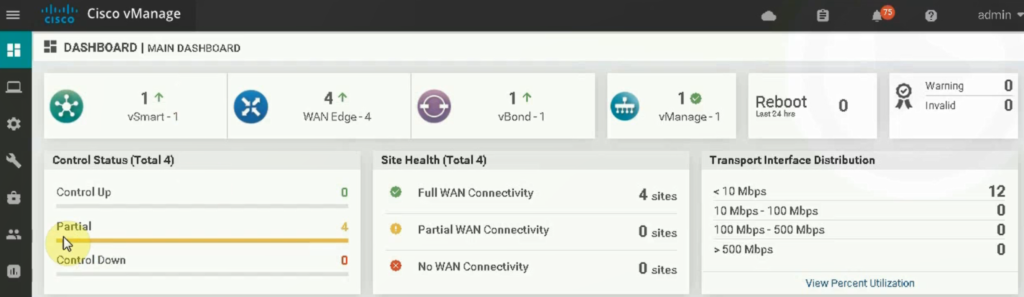
With applying the configuration, control status of WAN edge routers will be changed from Up to partial. It means that there is two transport but DTLS tunnel only over one of these transport is up.
This is because WAN edge routers still cannot connect to controllers over MPLS transport. In other words routing information through MPLS transport must be added to the infrastructure.
Add default Route through MPLS Transsport
In the next step, a default route will also be added through MPLS transport. This will be done through updating existing feature template, CSR1000v_VPN0.
device type: CSR1000v
Template: Cisco VPN
Template Name: CSR1000v_VPN0
Description: CSR1000v_VPN0
Section: IPV4 Route
Add second next-hop in default route through MPLS transport.
I have to add the explanation that my previous gateway 192.168.1.1 has some problems, so I have changed th gateway ip address to 192.168.1.2 in all WAN routers and controllers.
After routing information is updated, it is expected that control connections are again up.
Control connections can be checked in vBond and also through vManage Dashboard. Control connection should be now up through both internet and MPLS transport.
# show orchestrator connections