VXLAN EVPN COnfiguration Example1 based on cisco dcloud scenario
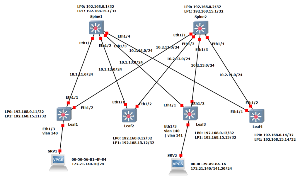
This is our topology on which we implement VXLAN EVPN. Please refer to the previous video for details.
VXLAN EVPN Configuration Example1 Steps
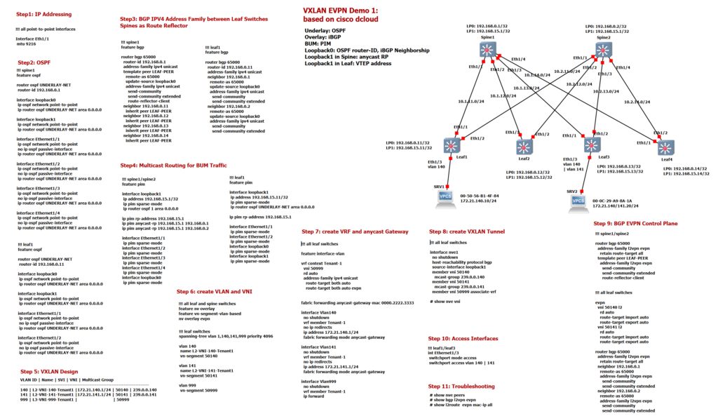
Our configurations are divided into 11 steps, in the previous section we checked the configuration of the underlay infrastructure including IP addressing, MTU, OSPF, iBGP and PIM sparse mode which are shown In Step1 to Step4. In this section we mainly focus on the configuration of overlay network in VXLAN EVPN.
VXLAN EVPN Configuration Example1 Step5
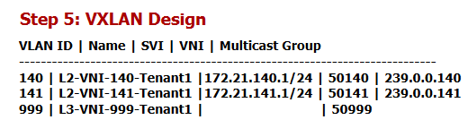
Just to review, Step 5 shows the design of our VXLAN EVPN demo. As you can see, we have two VLAN 140 and VLAN 141 mapped in leaf switches on VNI 50140 and VNI 50141. VLAN 999 is mapped to L3 VNI 50999, which is used for the VXLAN routing that we discussed theoretically in the previous sections. for each L2 VNI a specific multicast address is used to handle the BUM traffic. 239.0.0.140 for L2 VNI 50140 and 239.0.0.141 for L2 VNI 50141. The anycast gateway’s IP addresses for VLAN 140 and VLAN 141 are also 172.21.140.1 and 172.21.141.1 which the same address will be configured in all leaf switches.
VXLAN EVPN Configuration Example1 Step6
In step 6, the VXLAN EVPN feature is activated with three commands. In addition, VLAN 140, VLAN 141 and VLAN 999 are configured and the VLANs are assigned to the corresponding VNIs. VNI 50140 and VNI 50141 will be used as L2 VNI for L2 forwarding but VNI 50999 will be used as L3 VNI for inter-VXLAN routing.
!!! all leaf switches
feature nv overlay
feature vn-segment-vlan-based
nv overlay evpn


spanning-tree vlan 1,140,141,999 priority 4096

vlan 140
 name L2-VNI-140-Tenant1
 vn-segment 50140

vlan 141
 name L2-VNI-141-Tenant1
 vn-segment 50141

vlan 999
 vn-segment 50999
If the VXLAN network is connected to a traditional Layer 2 Ethernet network, spanning-tree commands make this VXLAN network to be the root of the STP topology.
VXLAN EVPN Configuration Example1 Step7
In step 7, VRF Tenant-1 and anycast gateway are implemented. For each VRF we configure a unique L3 VNI that is used for all inter-VXLAN routing. VNI 50999 is used in VRF Tenant-1 for L3 routing between different VNIs.
!!! all leaf switches
feature interface-vlan

vrf context Tenant-1
  vni 50999
  rd auto
  address-family ipv4 unicast
    route-target both auto
    route-target both auto evpn

fabric forwarding anycast-gateway-mac 0000.2222.3333

interface Vlan140
  no shutdown
  vrf member Tenant-1
  no ip redirects
  ip address 172.21.140.1/24
  fabric forwarding mode anycast-gateway

interface Vlan141
  no shutdown
  vrf member Tenant-1
  no ip redirects
  ip address 172.21.141.1/24
  fabric forwarding mode anycast-gateway

interface Vlan999
  no shutdown
  vrf member Tenant-1
  ip forward
RD and RT are automatically assigned in VRF. As you know, RD is used to solve the problem of overlapping IP addresses in different VRF. Router-ID and VRF-ID are placed in front of IP addresses when advertising via BGP.
RT are announced in BGP as a community so that the receiving leaf switch knows which routes have to be imported into which VRF. By default, the mixture of AS number and VNI number is used for the route-target. In the section, VXLAN EVPN control plane, we discussed the theory of RD and RT. Please refer to these videos if you would like to know more.
The anycast gateway VLAN 140 and VLAN 141 is configured with the same address in all leaf switches. here 172.21.140.1 for VLAN 140 and 172.21.141.1 for VLAN 141. So each endpoint can find its gateway in its own connecting leaf switch. The anycast-gateway keyword is used in all interface VLANs so that we don’t get a duplicate address error.
We have also configured the MAC address of the anycast gateway, which is the same not only in all leaf switches but also in all VLANs. This is not a problem, as MAC addresses only need to be unique in the VLAN scope.
All interface VLANs are members of VRF Tenant-1. VLAN 999 and its L3 VNI 50999 are also configured in this VRF for the purpose of inter-VXLAN routing.
VXLAN EVPN Configuration Example1 Step8
In step 8, VXLAN multipoint tunnel is created. The “host-reachability protocol BGP” command activates the EVPN address family in the VXLAN tunnel, which means that MAC addresses and IP addresses are learned via the BGP protocol in the control plane and not in the data plane. A multicast address is used for each L2 VNI because multicast routing is the method used in this demonstration to route BUM traffic. L3 VNI 50999 is also enabled for this tunnel to be used for inter-VXLAN routing.
!!! all leaf switches
interface nve1
  no shutdown
  host-reachability protocol bgp
  source-interface loopback1
  member vni 50140
    mcast-group 239.0.0.140
  member vni 50141
    mcast-group 239.0.0.141
  member vni 50999 associate-vrf
VXLAN EVPN Configuration Example1 Step9
In step 9, the address family L2VPN EVPN is activated in iBGP, which we have already configured in step 3. As you know, spine switches are route reflector and leaf switches are route reflector clients. Send community is activated in IBGP to send the route-target via iBGP as a community.
In this step EVPN is also activated for L2 VNI 50140 and 50141 and RD and RT are configured as Auto.
!!! spine1/spine2
router bgp 65000
  address-family l2vpn evpn
    retain route-target all
  template peer LEAF-PEER
    address-family l2vpn evpn
      send-community
      send-community extended
      route-reflector-client


!!! all leaf switches
router bgp 65000
  address-family l2vpn evpn
    retain route-target all
  neighbor 192.168.0.1
    remote-as 65000
    address-family l2vpn evpn
      send-community
      send-community extended
  neighbor 192.168.0.2
    remote-as 65000
    address-family l2vpn evpn
      send-community
      send-community extended

evpn
  vni 50140 l2
    rd auto
    route-target import auto
    route-target export auto
  vni 50141 l2
    rd auto
    route-target import auto
    route-target export auto
VXLAN EVPN Configuration Example1 Step10
In step 10 we want to test our VXLAN EVPN configuration. So we connect two servers to port Eth1/3 of the Leaf1 and Leaf3 switches. Server1 is added in VLAN 140, but Server2 is added once in VLAN 140 to check L2 connectivity between two servers over the VXLAN tunnel. and once in VLAN 141 to check the inter-VXLAN routing between these two servers via anycast gateway and L3 VNI.
VXLAN EVPN Configuration Example1 Step11
First let’s check the configuration of port Eth1/3 in both laf1 and leaf3 switch.
!!! leaf1/leaf3
int Ethernet1/3
 switchport mode access
 switchport access vlan 140 | 141


srv1 mac: 00-50-56-B1-4F-84
srv2 mac: 00-0C-29-A9-8A-1A
With the ping command we check both L2 connectivity and L3 connectivity.
With “show bgp l2vpn evpn”, we can check MAC and IP Addresses which are advertised through iBGP EVPN Address-Family.
leaf1# show bgp l2vpn evpn
BGP routing table information for VRF default, address family L2VPN EVPN
BGP table version is 470, Local Router ID is 192.168.0.11
Status: s-suppressed, x-deleted, S-stale, d-dampened, h-history, *-valid, >-best
Path type: i-internal, e-external, c-confed, l-local, a-aggregate, r-redist, I-i
njected
Origin codes: i - IGP, e - EGP, ? - incomplete, | - multipath, & - backup, 2 - b
est2

   Network            Next Hop            Metric     LocPrf     Weight Path
Route Distinguisher: 192.168.0.11:32907    (L2VNI 50140)
*>i[2]:[0]:[0]:[48]:[000c.29a9.8a1a]:[0]:[0.0.0.0]/216
                      192.168.15.13                     100          0 i
*>l[2]:[0]:[0]:[48]:[0050.56b1.4f84]:[0]:[0.0.0.0]/216
                      192.168.15.11                     100      32768 i
*>i[2]:[0]:[0]:[48]:[000c.29a9.8a1a]:[32]:[172.21.140.20]/272
                      192.168.15.13                     100          0 i
*>l[2]:[0]:[0]:[48]:[0050.56b1.4f84]:[32]:[172.21.140.10]/272
                      192.168.15.11                     100      32768 i

Route Distinguisher: 192.168.0.13:32907
*>i[2]:[0]:[0]:[48]:[000c.29a9.8a1a]:[0]:[0.0.0.0]/216
                      192.168.15.13                     100          0 i
* i                   192.168.15.13                     100          0 i
* i[2]:[0]:[0]:[48]:[000c.29a9.8a1a]:[32]:[172.21.140.20]/272
                      192.168.15.13                     100          0 i
*>i                   192.168.15.13                     100          0 i
MAC addresses of two servers are shown in the picture. The last octet of MAC address in server1 is 84 and the last octet of MAC address in server2 is 1A. as you can see these two MAC addressed are advertised through BGP EVPN Route Type 2.
In addition to MAC, IP, RD and L2 VNI are also shown in the output of “show bgp l2vpn evpn” command. As you know L3 VNI is also advertised through BGP EVPN Route Type 2. To see more detail, we can limit the output per prefix. For example “show bgp l2vpn evpn 172.21.141.20”
leaf1# show bgp l2vpn evpn 172.21.141.20
BGP routing table information for VRF default, address family L2VPN EVPN
Route Distinguisher: 192.168.0.11:32908    (L2VNI 50141)
BGP routing table entry for [2]:[0]:[0]:[48]:[000c.29a9.8a1a]:[32]:[172.21.141.2
0]/272, version 6326
Paths: (1 available, best #1)
Flags: (0x000212) (high32 00000000) on xmit-list, is in l2rib/evpn, is not in HW

  Advertised path-id 1
  Path type: internal, path is valid, is best path, no labeled nexthop, in rib
             Imported from 192.168.0.13:32908:[2]:[0]:[0]:[48]:[000c.29a9.8a1a]:
[32]:[172.21.141.20]/272
  AS-Path: NONE, path sourced internal to AS
    192.168.15.13 (metric 81) from 192.168.0.1 (192.168.0.1)
      Origin IGP, MED not set, localpref 100, weight 0
      Received label 50141 50999
      Extcommunity: RT:65000:50141 RT:65000:50999 ENCAP:8 Router MAC:000c.2954.0
dba
      Originator: 192.168.0.13 Cluster list: 192.168.0.1

  Path-id 1 not advertised to any peer

Route Distinguisher: 192.168.0.13:32908
BGP routing table entry for [2]:[0]:[0]:[48]:[000c.29a9.8a1a]:[32]:[172.21.141.2
0]/272, version 6327
Paths: (2 available, best #2)
Flags: (0x000202) (high32 00000000) on xmit-list, is not in l2rib/evpn, is not i
n HW

  Path type: internal, path is valid, not best reason: Neighbor Address, no labe
led nexthop
  AS-Path: NONE, path sourced internal to AS
    192.168.15.13 (metric 81) from 192.168.0.2 (192.168.0.2)
      Origin IGP, MED not set, localpref 100, weight 0
      Received label 50141 50999
      Extcommunity: RT:65000:50141 RT:65000:50999 ENCAP:8 Router MAC:000c.2954.0
dba
      Originator: 192.168.0.13 Cluster list: 192.168.0.2

  Advertised path-id 1
  Path type: internal, path is valid, is best path, no labeled nexthop
             Imported to 2 destination(s)
  AS-Path: NONE, path sourced internal to AS
    192.168.15.13 (metric 81) from 192.168.0.1 (192.168.0.1)
      Origin IGP, MED not set, localpref 100, weight 0
      Received label 50141 50999
      Extcommunity: RT:65000:50141 RT:65000:50999 ENCAP:8 Router MAC:000c.2954.0
dba
      Originator: 192.168.0.13 Cluster list: 192.168.0.1

  Path-id 1 not advertised to any peer
To monitor VXLAN tunnel itself, we have also a few commands. “show nve interface” shows your NVE interface number and if it is up.
leaf1# show nve interface
Interface: nve1, State: Up, encapsulation: VXLAN
 VPC Capability: VPC-VIP-Only [not-notified]
 Local Router MAC: 000c.296e.62c9
 Host Learning Mode: Control-Plane
 Source-Interface: loopback1 (primary: 192.168.15.11, secondary: 0.0.0.0)
“show nve peers” displays VXLAN tunnel peers only after VXLAN traffic traverses through the router. We have only transferred traffic through VXLAN tunnel between server1 and server2 which are connected to leaf1 and leaf3. So it shows here only leaf3 as the only peer.
leaf1# show nve peers
Interface Peer-IP          State LearnType Uptime   Router-Mac
--------- ---------------  ----- --------- -------- -----------------
nve1      192.168.15.13    Up    CP        1d00h    000c.2954.0dba
To display list of all VNIs that are associated with various NVE interfaces and the associated multicast IP address that is used for multi-destination frames, use the “show nve vni” command. As you can see, L2 VNI, 50140 and 50141 and associated multicast address is shown here. L3 VNI 5099 is also displayed in the output. State of all VNI are also UP.
leaf1# show nve vni
Codes: CP - Control Plane        DP - Data Plane
       UC - Unconfigured         SA - Suppress ARP
       SU - Suppress Unknown Unicast
       Xconn - Crossconnect
       MS-IR - Multisite Ingress Replication

Interface VNI      Multicast-group   State Mode Type [BD/VRF]      Flags
--------- -------- ----------------- ----- ---- ------------------ -----
nve1      50140    239.0.0.140       Up    CP   L2 [140]
nve1      50141    239.0.0.141       Up    CP   L2 [141]
nve1      50999    n/a               Up    CP   L3 [Tenant-1]
To view MAC and IP address information learnt by the switch in the EVPN control plane, use the “show l2route evpn mac-ip all” command. As you can see, the output shows MAC and IP learned through BGP EVPN and also their next-hop address.
leaf1#  show l2route evpn mac-ip all
Flags -(Rmac):Router MAC (Stt):Static (L):Local (R):Remote (V):vPC link
(Dup):Duplicate (Spl):Split (Rcv):Recv(D):Del Pending (S):Stale (C):Clear
(Ps):Peer Sync (Ro):Re-Originated (Orp):Orphan
Topology    Mac Address    Host IP         Prod   Flags         Seq No     Next-
Hops
----------- -------------- --------------- ------ ---------- ---------------
140         0050.56b1.4f84 172.21.140.10   HMM    --            0         Local

140         000c.29a9.8a1a 172.21.140.20   BGP    --            0         192.168.15.13
Excellent goods from you, man. I’ve understand your stuff previous to and you’re just too great. I really like what you have acquired here, certainly like what you are stating and the way in which you say it. You make it enjoyable and you still take care of to keep it sensible. I can not wait to read much more from you. This is really a terrific website. snokilkirt.com