Juniper Routing Instance has the same concept of VRF in Cisco routers, which allows us to use a single physical router as multiple logical routers.
All logical routers in control plane and data plane are completely separate, so it can be assumed that there are actually multiple physical routers. The only difference is that the management plane is shared between routing instances (logical routers).
Juniper Routing Instance Overview
As explained earlier, with Juniper Routing Instance exactly like VRF, you don’t need to use multiple routers for multiple purposes or multiple customers. Instead, you can use just one physical router with multiple routing instances, each for a purpose or customer.
Juniper Routing Instance Applications
Some of the applications are somehow displayed in this figure.
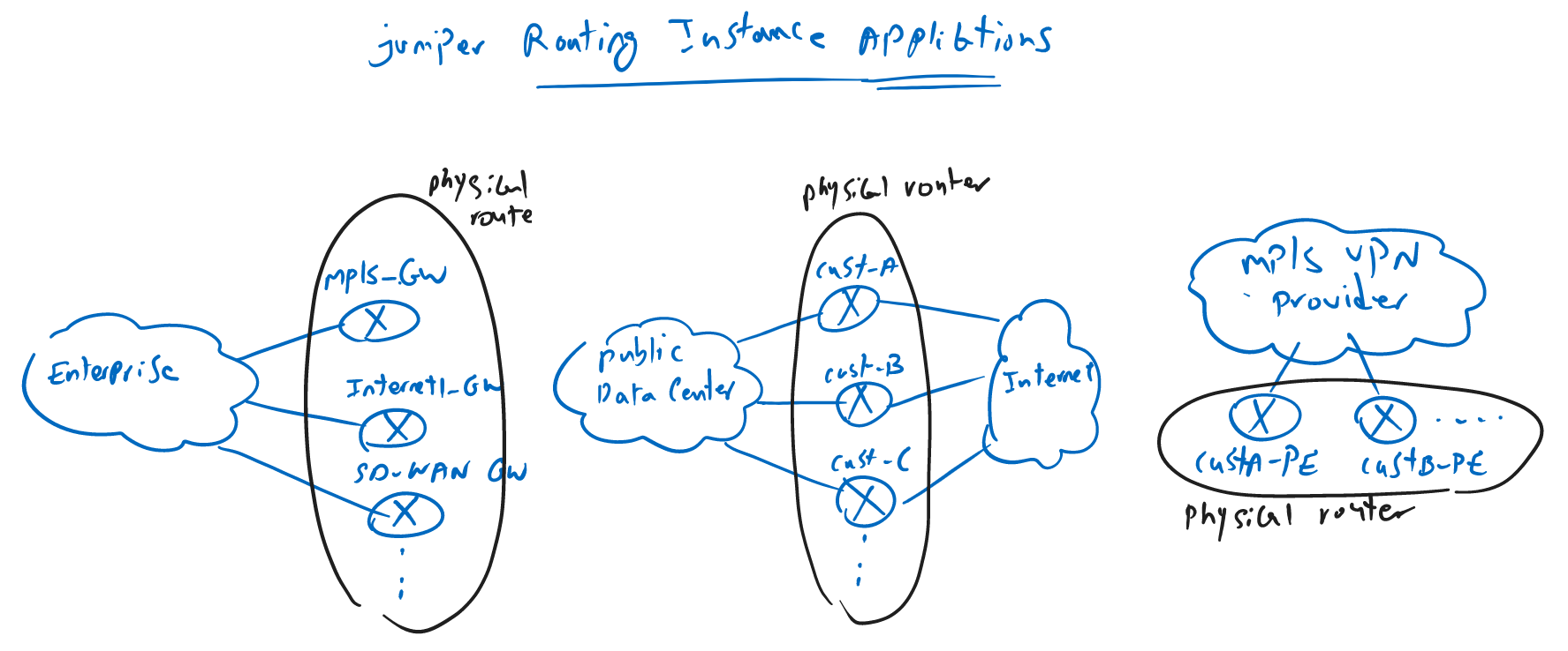
As a first example, a company does not need to install multiple physical gateways for MPLS gateway, Internet gateway and SD-WAN gateway. A logical routing instance can be used for each of these gateways.
In the second example, a public data center provides each customer with a separate router with their own BGP configuration to the Internet ISP neighbors. Instead, multiple routing instances will be used.
In the third example, an MPLS VPN service provider, uses a separate routing instance for each customer to install their routing information and advertise across the service provider’s network.
Juniper Routing Instance Overview
Two routing instances are usually preconfigured in the router at the factory. default and management.
By default, the management interface is a member of the management routing instance and all other interfaces are members of the default routing instance.

You can create as many routing instances as you need in your network according to the resource limitation. each routing instance is completely isolated from other routing instances in terms of control plane and data plane.
In the control plane, you use an independent routing protocol and routing table for each routing instance. This figure assumes that an independent OSPF is used in the default and routing instance 1. Management routing instance uses static to handle the routing and routing instance 2 uses ISIS as its own routing protocols. The routes learned in each routing instance are stored in an independent routing table.
In the data plane each routing instances has its own interfaces and forwarding tables. Interfaces can be physical, sub interfaces, or logical interfaces assigned to each routing instance.
When a traffic is received in an interface in the router, depending on which routing instance this interface belongs to, the traffic is processed and forwarded based on the corresponding forwarding table.
The only section shared by routing instances is the management plane. When an administrator connects to the device, it can manage all routing instances, independently of the routing instance that the administrator owns. In other words, an administrator belonging to the customer A with routing instance 2 can also view and manage other instances.
Sample Routing Instance topology
To configure a routing instance example, I have prepared a sample topology with two isolated networks, but simulated by a shared physical router pairs between these two networks.

In the first network, two loopback interfaces with IP addresses 172.16.1.1/24 and 172.16.2.1/24 will connect to each other through two routers connected to each other with a link with IP address range, 10.10.10.0/24. In this network, all interfaces are in the same common trust zone.
In the second network, two loopback interfaces with IP addresses 172.17.1.1/24 and 172.17.2.1/24 will connect to each other through two routers connected to each other with a link with IP address range, 20.20.20.0/24. In this network, all interfaces are in the same common trust1 zone.
These two networks will be implemented with just one pair physical router and with the help of routing instances.
The first network will use default routing instance. That means we will not change any thing for the first network since by default al interfaces are in default routing instance.
For the second network, we will create a new routing instance with the name of “A”. interfaces related to the second network will be reassigned to this new routing instance.
Static routing will be used for each instance independently to handle routing so the loopback interfaces can reach each other.
Juniper Routing Instance Configuration
All previous configurations including routing, routing protocol and interfaces are deleted from the configuration.
To start the configuration, we first configure the IP address of interfaces ge-0/0/0 and loopback0.0 in the default routing instance. the interface are in the default routing instance by default and we only provide the IP addresses as shown in the topology.
We will also add the interfaces into trust zone and enable host-inbound traffic for ping and traceroute connectivity check.
!!! vSRX1
set interfaces ge-0/0/0 unit 0 family inet address 10.10.10.1/24
set interfaces lo0 unit 0 family inet address 172.16.1.1/24
set security zones security-zone trust interfaces lo0.0 host-inbound-traffic system-services all
set security zones security-zone trust interfaces ge-0/0/0.0 host-inbound-traffic system-services all


!!! vSRX2
set interfaces ge-0/0/0 unit 0 family inet address 10.10.10.2/24
set interfaces lo0 unit 0 family inet address 172.16.2.1/24
set security zones security-zone trust interfaces lo0.0  host-inbound-traffic system-services all
set security zones security-zone trust interfaces ge-0/0/0.0 host-inbound-traffic system-services all
In the second step we will create a new routing-instance, “A”, and add interfaces ge-0/0/1 and loopback0.1 in the new routing instance.
The types of routing instance is virtual-router. We have different types of routing instances for different applications which is not discussed in this course.
Then we will give the IP address of the interfaces in the new instance as it is shown in the topology. we will also add a new security zone, “trust1”, add all interfaces in routing instance “A” in the zone “trust1” and enable host-inbound traffic.
!!! vSRX1
set routing-instances A instance-type virtual-router interface ge-0/0/1
set routing-instances A instance-type virtual-router interface lo0.1

set interfaces ge-0/0/1 unit 0 family inet address 20.20.20.1/24
set interfaces lo0 unit 1 family inet address 172.17.1.1/24

set security zones security-zone trust1 interfaces ge-0/0/1.0 host-inbound-traffic system-services all
set security zones security-zone trust1 interfaces lo0.1 host-inbound-traffic system-services all


!!! vSRX2
set routing-instances A instance-type virtual-router interface ge-0/0/1
set routing-instances A instance-type virtual-router interface lo0.1

set interfaces ge-0/0/1 unit 0 family inet address 20.20.20.2/24
set interfaces lo0 unit 1 family inet address 172.17.2.1/24

set security zones security-zone trust1 interfaces ge-0/0/1.0 host-inbound-traffic system-services all
set security zones security-zone trust1 interfaces lo0.1 host-inbound-traffic system-services all
For the new zone “trust1”, there is no default policy to permit everything and we have to create a new policy to permit all traffic between interfaces in the same new zone, trust1.
!!! vSRX1
set security policies from-zone trust1 to-zone trust1 policy default-permit match source-address any
set security policies from-zone trust1 to-zone trust1 policy default-permit match destination-address any
set security policies from-zone trust1 to-zone trust1 policy default-permit match application any
set security policies from-zone trust1 to-zone trust1 policy default-permit then permit


!!! vSRX2
set security policies from-zone trust1 to-zone trust1 policy default-permit match source-address any
set security policies from-zone trust1 to-zone trust1 policy default-permit match destination-address any
set security policies from-zone trust1 to-zone trust1 policy default-permit match application any
set security policies from-zone trust1 to-zone trust1 policy default-permit then permit
With the command “show route instance” in operational mode, we can check routing instances.
rayka@vSRX2# run show route instance
Instance             Type
         Primary RIB                                     Active/holddown/hidden
master               forwarding
         inet.0                                          7/0/0
         inet6.0                                         1/0/0

A                    virtual-router
         A.inet.0                                        5/0/0
         A.inet6.0                                       1/0/0

__juniper_private1__ forwarding
         __juniper_private1__.inet.0                     6/0/0

__juniper_private2__ forwarding
         __juniper_private2__.inet.0                     0/0/1

__juniper_private3__ forwarding

__juniper_private4__ forwarding
         __juniper_private4__.inet.0                     2/0/0

__master.anon__      forwarding

mgmt_junos           forwarding
As you can see, there are routing instances, “master” and “mgmt_junos”, which are created by the factory. There is also a new routing instance, “A”, which we have already configured.
With the command “show interfaces terse routing-instance all”, we can check which interfaces to which routing instances are assigned.
rayka@vSRX1# run show interfaces terse routing-instance all
Interface        Admin Link Proto           Local                Instance
ge-0/0/0.0       up    up   inet      10.10.10.1/24
                                                                 default
sp-0/0/0.0       up    up   inet
                            inet6                                default
sp-0/0/0.16383   up    up   inet                                 __juniper_private1__
ge-0/0/1.0       up    up   inet      20.20.20.1/24
                                                                 A
em0.0            up    up   inet      128.0.0.1/2
                                                                 __juniper_private1__
em1.32768        up    up   inet      192.168.1.2/24
                                                                 __juniper_private4__
fxp0.0           up    up   inet      192.168.200.101/24
                                                                 default
lo0.0            up    up   inet      172.16.1.1/24
                                                                 default
lo0.1            up    up   inet      172.17.1.1/24
                                                                 A
lo0.16384        up    up   inet      127.0.0.1                  __juniper_private2__
lo0.16385        up    up   inet      10.0.0.1
                                      10.0.0.16
                                      128.0.0.1
                                      128.0.0.4
                                      128.0.1.16                 __juniper_private1__
With the command “show interfaces terse routing-instance A”, we can check which interfaces to routing instances “A” are assigned.
rayka@vSRX1# run show interfaces terse routing-instance A
Interface               Admin Link Proto    Local                 Remote
ge-0/0/1.0              up    up   inet     20.20.20.1/24
lo0.1                   up    up   inet     172.17.1.1/24
As you can see, interfaces ge-0/0/0 and lo0.0 are in the default routing instance and interfaces ge-0/0/1 and lo0.1 are in the new created, “A” routing instance.
To make sure that links connecting routers to each other are up, we can ping the other side of the connection. But to ping the other side of the link belonging to the routing instance “A”, we need to use ping command in the routing instance.
rayka@vSRX1# run ping 10.10.10.2
PING 10.10.10.2 (10.10.10.2): 56 data bytes
64 bytes from 10.10.10.2: icmp_seq=0 ttl=64 time=1.973 ms
^C
--- 10.10.10.2 ping statistics ---
1 packets transmitted, 1 packets received, 0% packet loss
round-trip min/avg/max/stddev = 1.973/1.973/1.973/0.000 m
!
rayka@vSRX1# run ping 20.20.20.2 routing-instance A
PING 20.20.20.2 (20.20.20.2): 56 data bytes
64 bytes from 20.20.20.2: icmp_seq=0 ttl=64 time=2.028 ms
64 bytes from 20.20.20.2: icmp_seq=1 ttl=64 time=1.460 ms
^C
--- 20.20.20.2 ping statistics ---
2 packets transmitted, 2 packets received, 0% packet loss
round-trip min/avg/max/stddev = 1.460/1.744/2.028/0.284 ms
To make loopback interfaces to reach each other, we need to create the required routing information.
For the default routing instance, we create the routing information as we have learned in the previous section.
But for the routing instance, “A”, the routing information must be create inside the routing instance.
!!! vSRX1
set routing-options static route 172.16.2.0/24 next-hop 10.10.10.2
set routing-instances A routing-options static route 172.17.2.0/24 next-hop 20.20.20.2


!!! vSRX2
set routing-options static route 172.16.1.0/24 next-hop 10.10.10.1
set routing-instances A routing-options static route 172.17.1.0/24 next-hop 20.20.20.1
After creating the routes in routing table, we can check the default routing instance routing table with the command “show route”. But for the routing instance, “A”, the command, “show route table A.inet.0”
rayka@vSRX2# run show route table A.inet.0

A.inet.0: 5 destinations, 5 routes (5 active, 0 holddown, 0 hidden)
+ = Active Route, - = Last Active, * = Both

20.20.20.0/24      *[Direct/0] 00:22:42
                    >  via ge-0/0/1.0
20.20.20.2/32      *[Local/0] 00:22:42
                       Local via ge-0/0/1.0
172.17.1.0/24      *[Static/5] 00:02:56
                    >  to 20.20.20.1 via ge-0/0/1.0
172.17.2.0/24      *[Direct/0] 00:22:42
                    >  via lo0.1
172.17.2.1/32      *[Local/0] 00:22:42
                       Local via lo0.1
As you can see, with “show route” command in each routing instance, the routes only related to that “routing-instance” will be displayed.
In the default routing table, the routes to destinations 172.16.1.0/24 and 172.16.2.0/24 are in the routing table.
In the routing instance “A” routing table, the routes to destinations 172.17.1.0/24 and 172.17.2.0/24 are stored in the routing table.
With ping and traceroute command in the default routing-instance or configured routing instance, you can make sure of the connectivity between loopback interfaces.
rayka@vSRX1# run ping 172.17.2.1 routing-instance A source 172.17.1.1
PING 172.17.2.1 (172.17.2.1): 56 data bytes
64 bytes from 172.17.2.1: icmp_seq=0 ttl=64 time=1.515 ms
64 bytes from 172.17.2.1: icmp_seq=1 ttl=64 time=1.634 ms
64 bytes from 172.17.2.1: icmp_seq=2 ttl=64 time=6.122 ms
64 bytes from 172.17.2.1: icmp_seq=3 ttl=64 time=1.827 ms
^C
--- 172.17.2.1 ping statistics ---
4 packets transmitted, 4 packets received, 0% packet loss
round-trip min/avg/max/stddev = 1.515/2.775/6.122/1.936 ms

[edit]
rayka@vSRX1# run traceroute 172.17.2.1 routing-instance A source 172.17.1.1
traceroute to 172.17.2.1 (172.17.2.1) from 172.17.1.1, 30 hops max, 52 byte packets
 1  172.17.2.1 (172.17.2.1)  3.167 ms  2.686 ms  3.045 ms
This is very helpful thank you ,
just have a question how do you assign multiple loop back addresses to routing instances .
Thanks
Hi. Thanks
interface loopback 0 unit 0 …
interface loopback 0 unit 1 …
…
set routing-instances A instance-type virtual-router interface lo0.0
set routing-instances A instance-type virtual-router interface lo0.1
…