Juniper firewall filter is a Junos security solution to filter or control traffic at the data plane as they enter or exit an interface. It is exactly the same as access control list in Cisco devices.
The firewall filter is stateless, so it differs from the stateful Juniper security policy which is stateful. In other words, in firewall filter each packet must be inspected individually to determine whether it is permitted to be transmitted or it must be filtered.
Juniper Firewall Filter Fundamental
as it is explained in the introduction, Juniper Firewall Filter allows us to control traffic at layer 3 and layer 4 where they are permitted or filtered as they enter or exit an interface.
Juniper Firewall Filter Building Blocks
From a configuration perspective, it is exactly implemented like routing policy, what we have learned in in the previous section.
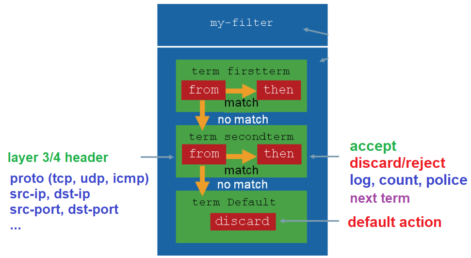
We write a firewall filter with the rules or terms which are processed in order.
Each term has a “from” statement to match the traffic at layer 3 and layer 4. Source and destination IP address, Protocol and destination ports are the most usual headers that are inspected to match the packets.
Each term also has an “action” statement to take an action when a traffic is matched. Permit and deny are the most usual actions to be applied to the packet.
To deny the packet, we have two options. “discard” and “reject”. With discard action, the packet is discarded silently without giving any notification. But with reject action, an ICMP notification will be sent to the source of the packet which is discarded.
We may also log, count, or limit the rate of specific traffic. If these actions are configured, the packet will be forwarded after the action is applied. If you want to discard the traffic after applying these action, this must be explicitly configured.
The action can be configured as “next term”, which means that processing continues with the next rule.
When the traffic is not matched with any of the configured rules, by default it will be discarded.
Juniper Firewall Filter Configuration procedure
To better understand Firewall Filter, This is an example taken from juniper website.
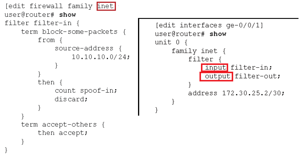
Firewall filters can be configured separately for IPv4 and IPv6. This example is configured under the “inet” family, which is dedicated to IPv4.
The name of firewall filter is “filter-in”. it has two terms, “block-some-packets” and “accept others”. In the first rule, traffic with the source address 10.10.10.0/24 are counted and discarded. All other packets are permitted with the second term.
Firewall filter must be applied to an interface in incoming or outgoing direction. In the right section of photo, it shows how firewall filter, “filter-in”, is applied to the interface ge-0/0/1 and in incoming direction.
Juniper Firewall Filter configuration Example
Now we will implement a sample firewall filter in vSRX devices.
Firewall Filter Topology review
This is the topology that we are going to apply the firewall filter.
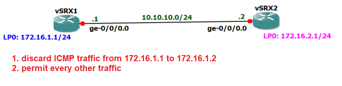
There are two vSRX devices connected to each other through ge-0/0/0 interface with IP subnet 10.10.10.0/24. Each vSRX devices has a loopback interface. Loopback interface connected to vSRX1 has the IP address of 172.16.1.1/24 and loopback interface connected to vSRX2 has the IP address of 172.16.2.1/24.
Routing between these two devices is already configured in previous sections and loopback interfaces are now reachable over the link connecting two vSRX devices to each other.
In this example we want to configure a very simple firewall filter to drop any ICMP traffic from the source 172.16.1.1 to the destination 172.16.2.1. all other traffic will be permitted.
We write the firewall filter in vSRX2 and apply it to the ge-0/0/0 interface and in the incoming direction.
Juniper Firewall Filter configuration
Before starting the configuration, let’s ping and also test SSH connection between these two loopback interfaces to make sure that every traffic is permitted before firewall filter is configured and applied to the device.
rayka@vSRX1# run ping 172.16.2.1 source 172.16.1.1
PING 172.16.2.1 (172.16.2.1): 56 data bytes
64 bytes from 172.16.2.1: icmp_seq=0 ttl=64 time=1.859 ms
64 bytes from 172.16.2.1: icmp_seq=1 ttl=64 time=2.284 ms
64 bytes from 172.16.2.1: icmp_seq=2 ttl=64 time=1.464 ms
^C
--- 172.16.2.1 ping statistics ---
3 packets transmitted, 3 packets received, 0% packet loss
round-trip min/avg/max/stddev = 1.464/1.869/2.284/0.335 ms

[edit]
rayka@vSRX1# run ping 172.16.2.1
PING 172.16.2.1 (172.16.2.1): 56 data bytes
64 bytes from 172.16.2.1: icmp_seq=0 ttl=64 time=1.869 ms
64 bytes from 172.16.2.1: icmp_seq=1 ttl=64 time=2.396 ms
64 bytes from 172.16.2.1: icmp_seq=2 ttl=64 time=1.587 ms
^C
--- 172.16.2.1 ping statistics ---
3 packets transmitted, 3 packets received, 0% packet loss
round-trip min/avg/max/stddev = 1.587/1.951/2.396/0.335 ms

[edit]
rayka@vSRX1# run ssh [email protected]
Password:
Last login: Sat Jun 25 17:34:29 2022 from 10.10.10.1
--- JUNOS 22.1R1.10 Kernel 64-bit  JNPR-12.1-20220221.2b3c81a_buil
rayka@vSRX2>

rayka@vSRX2> exit

Connection to 172.16.2.1 closed.
This is the configuration that I have already prepared to configure in vSRX2.
We configure a filter with the name of “FILTER1” . it has two terms, “DISCARD-ICMP” and “PERMIT-ALL”.
In the first term, “DISCARD ICMP”, we reject any icmp traffic from vSRX1 loopback interfaces with source address of 172.16.1.1 to the destination vSRX2 loopback interface with IP address 172.16.2.1.
In the second term. “PERMIT-ALL”, we permit every other traffic.
The firewall filter, “FILTER1” is applied in incoming direction of interface, ge-0/0/0 in vSRX2 router.
rayka@vSRX2# run show configuration | display set | grep filter
set interfaces ge-0/0/0 unit 0 family inet filter input FILTER1
set firewall family inet filter FILTER1 term DISCARD-ICMP from source-address 172.16.1.1/32
set firewall family inet filter FILTER1 term DISCARD-ICMP from destination-address 172.16.2.1/32
set firewall family inet filter FILTER1 term DISCARD-ICMP from protocol icmp
set firewall family inet filter FILTER1 term DISCARD-ICMP then reject
set firewall family inet filter FILTER1 term PERMIT-ALL then accept

[edit]
rayka@vSRX2#
!
rayka@vSRX2# show | compare
[edit interfaces ge-0/0/0 unit 0 family inet]
+       filter {
+           input FILTER1;
+       }
[edit]
+  firewall {
+      family inet {
+          filter FILTER1 {
+              term DISCARD-ICMP {
+                  from {
+                      source-address {
+                          172.16.1.1/32;
+                      }
+                      destination-address {
+                          172.16.2.1/32;
+                      }
+                      protocol icmp;
+                  }
+                  then {
+                      reject;
+                  }
+              }
+              term PERMIT-ALL {
+                  then accept;
+              }
+          }
+      }
+  }

[edit]
rayka@vSRX2#
After applying the configuration, to see the result of the configuration, we send ping and ssh traffic from vSRX1 to vSRX2.
rayka@vSRX1# run ping 172.16.2.1 source 172.16.1.1
PING 172.16.2.1 (172.16.2.1): 56 data bytes
36 bytes from 10.10.10.2: Communication prohibited by filter
Vr HL TOS  Len   ID Flg  off TTL Pro  cks      Src      Dst
 4  5  00 0054 5f25   0 0000  40  01 c061 172.16.1.1  172.16.2.1

36 bytes from 10.10.10.2: Communication prohibited by filter
Vr HL TOS  Len   ID Flg  off TTL Pro  cks      Src      Dst
 4  5  00 0054 5f47   0 0000  40  01 c03f 172.16.1.1  172.16.2.1

36 bytes from 10.10.10.2: Communication prohibited by filter
Vr HL TOS  Len   ID Flg  off TTL Pro  cks      Src      Dst
 4  5  00 0054 5f5b   0 0000  40  01 c02b 172.16.1.1  172.16.2.1

^C
--- 172.16.2.1 ping statistics ---
3 packets transmitted, 0 packets received, 100% packet loss

[edit]
rayka@vSRX1# run ping 172.16.2.1
PING 172.16.2.1 (172.16.2.1): 56 data bytes
64 bytes from 172.16.2.1: icmp_seq=0 ttl=64 time=1.883 ms
64 bytes from 172.16.2.1: icmp_seq=1 ttl=64 time=1.894 ms
64 bytes from 172.16.2.1: icmp_seq=2 ttl=64 time=1.447 ms
^C
--- 172.16.2.1 ping statistics ---
3 packets transmitted, 3 packets received, 0% packet loss
round-trip min/avg/max/stddev = 1.447/1.741/1.894/0.208 ms

[edit]
rayka@vSRX1# run ssh [email protected]
Password:
Last login: Sat Jun 25 17:56:46 2022 from 10.10.10.1
--- JUNOS 22.1R1.10 Kernel 64-bit  JNPR-12.1-20220221.2b3c81a_buil

rayka@vSRX2>
As you can see, ping traffic from 172.16.1.1 to destination 172.16.2.1 is rejected and an icmp notification is returned to the vSRX1. Because of that vSRX1 knows that it is rejected by 10.10.10.2.
But ping traffic with the source address of default outgoing interface is not discarded.
SSH traffic is permitted as we expect since we have permitted all other traffic in the second term.