ISIS LSP types and database exchange detail is what we discuss after adjacency comes up in ISIS and it is the topic of this section.
To better understand database exchange process in ISIS routing protocol, we will compare ISIS packets with OSPF packets, ISIS LSP types with OSPF LSA types and finally we will have a configuration example to demonstrate ISIS LSP packet details.
ISIS LSP Types and Database Exchange Fundamental
In the ISIS protocol, like other routing protocols, after the adjacency between the routers is established, the database exchange between the neighboring routers begins.
ISIS Packet Types versus OSPF Packet Types
However ISIS protocol is designed independently of the OSPF protocol, but they are very similar and a comparison between them can help us understand the ISIS protocol better.
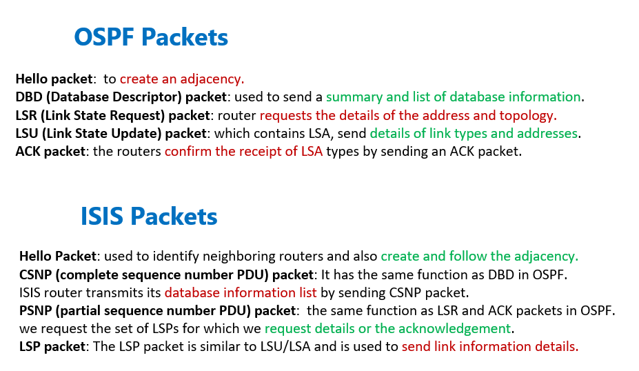
If you remember, there are five types of packets with different target in the OSPF protocol.
- The Hello packet is to create an adjacency.
- The DBD (Database Descriptor) packet is used to send a summary and list of database information existing in the router.
- By sending the LSR (Link State Request) packet, the router requests the details of the address and topology of the links that are received in the DBD but are not present in the router’s database table.
- The LSU (Link State Update) packet, which contains LSA, is used to send details of link types and addresses.
- Finally, since the database information is transferred reliably in OSPF, the routers confirm the receipt of LSA types by sending an ACK packet.
Almost equivalent to the OSPF packets are also available in ISIS:
- Hello Packet: It is used to identify neighboring routers and also create and follow the adjacency.
- CSNP (complete sequence number PDU) packet: It has the same function as DBD in OSPF.
ISIS router transmits its database information list by sending CSNP packet.
In point-to-point networks, the CSNP packet is sent only once at the beginning of creating an adjacency, but in broadcast networks, as we will see later, this packet is sent periodically by DIS.
It should be noted that the word Sequence Number in the two words CSNP and PSNP has nothing to do with the Sequence Number field of the LSP packet and only refers to the set of LSPs whose information are inside this packet.
- PSNP (partial sequence number PDU) packet: has the same function as LSR and ACK packets in OSPF.
Inside PSNP packet, we refer to the set of LSPs for which we request details or acknowledgement.
Of course, as we will discuss later, in broadcast networks, acknowledge is sent by CSNP (not PSNP).
- LSP packet: The LSP packet is similar to LSU/LSA and is used to send link information details.
ISIS LSP Types versus OSPF LSA/LSU Types
In OSPF, the link and address information is packed into the LSA, but the LSA is not sent. Instead, a set of LSAs is sent by the LSU packet.
In other words, in OSPF, the unit of link information is LSA, and dependent on the type of link information, there are different types of LSA.
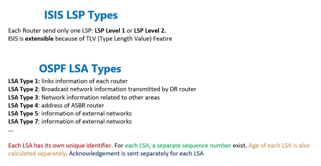
With ISIS, the situation is somehow different. In ISIS the link status information packet is called LSP and all information are sent through LSP Level 1 packet or through LSP Level 2 packet. The link and address information are placed in the related TLV fields within the LSP. This is unlike OSPF, that we have about ten different types of LSA.
ISIS LSP Types versus OSPF LSA/LSU Types
To compare LSP and LSA, there are different types of LSA in OSPF.
Each LSA has its own unique identifier. For each LSA, a separate sequence number exist. Age of each LSA is also calculated separately. Acknowledgement is sent separately for each LSA. In short, there are many LSAs in OSPF and each LSA is processed separately.
But in ISIS there is only one LSP per router. And all links and addresses of each router are sent only in the format of one LSP. For all the links and addresses of each router, there is only one sequence number. Acknowledgement is sent only once, and in short, only one LSP is processed per router in ISIS.
It is interesting to know that for processing reason, in OSPF, there can be a maximum of 50 routers in each area, but in ISIS, the number of allowed routers in each area is 1000 routers.
In OSPF, links information of each router is sent with LSA Type 1. Broadcast network information is transmitted by LSA Type 2 by DR router. Network information related to other areas is sent with LSA Type 3 and finally the information of external networks is transferred with LSA Type 5 and LSA Type 7.
In ISIS, all this information is sent only in one LSP. Of course, in broadcast networks, the DIS router also creates and sends a Pseudo LSP that introduces the topology of the broadcast network. We will talk about it in a separate section related to broadcast networks. The fact that all the information of each router is transmitted by only one LSP also has the disadvantage that if only one TLV is changed, the LSP that includes all TLVs is re-sent.
ISIS LSP identifiers (System-Id, Pseudonode-Id and fragment-Id)
Another question that may arise in your mind is that if the number of links and addresses that are to be sent with only one LSP is too large, then the LSP packet size will exceed the maximum allowed size of the interface (MTU). In this case, how is the LSP packet sent on the link?
If the LSP packet size exceeds the link MTU size, it is still one LSP packet and it fragments LSP packet into multiple smaller LSP packets, but all with the same identifier. In other words all LSPs have the same System-Id and Pseudonode Id, and only fragmentation number is different.
Probably, by using the words System-Id, Pseudonode-Id and fragment-Id, you are confused, what are these terms? If you remember, in OSPF, each LSA is distinguished from the others by its type and Link-State ID. In ISIS, each LSP is distinguished by these three fields.
System ID: This field indicates the system-Id of the router that sent this LSP.
Pseudonode ID: Normally, the value of this field is zero, but in the Pseudonode LSP sent by DIS, it refers to the System-Id of the DIS router. we will talk about DIS in broadcast network.
LSP Number: This field shows the fragment number of the LSP packet. When the size of the LSP packet is larger than the MTU size of the interface, the LSP packet is divided into smaller parts and each part is separated from the other by a fragment number.
ISIS LSP Packet demonstration
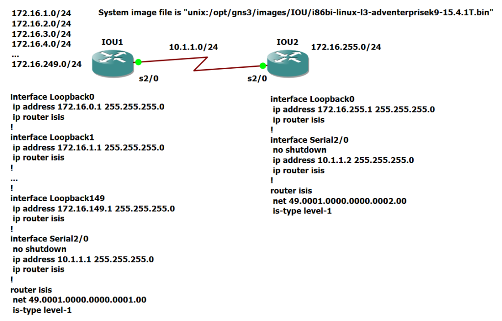
To better understand LSP packet and LSP identifiers, look at this topology, in which router IOU1 is connected to router IOU2 in a point-to-point manner, and 150 loopback interfaces are configured on router IOU1. Then the ISIS protocol is activated on both routers and interfaces.
!!! IOU1
interface Loopback0
 ip address 172.16.0.1 255.255.255.0
 ip router isis
!
interface Loopback1
 ip address 172.16.1.1 255.255.255.0
 ip router isis
!
...
!
interface Loopback149
 ip address 172.16.149.1 255.255.255.0
 ip router isis
!
interface Serial2/0
 no shutdown
 ip address 10.1.1.1 255.255.255.0
 ip router isis
!
router isis
 net 49.0001.0000.0000.0001.00
 is-type level-1


!!! IOU2
interface Loopback0
 ip address 172.16.255.1 255.255.255.0
 ip router isis
!
interface Serial2/0
 no shutdown
 ip address 10.1.1.2 255.255.255.0
 ip router isis
!
router isis
 net 49.0001.0000.0000.0002.00
 is-type level-1
With the command “show isis hostname” is, the system-id and its equivalent hostname are displayed in the output. The sign * next to the router name indicates the current router. This output is important for us because in the output of show commands mainly used hostname instead of system-id.
IOU1#show isis hostname
Level  System ID      Dynamic Hostname  (notag)
     * 0000.0000.0001 IOU1
 1     0000.0000.0002 IOU2
IOU1#
“show isis database” output and LSP identifier
In the output of “show isis database“, Level-1 database table of the first router is displayed. The database table output includes only Level-1 information because IOU1 and IOU2 routers have already been configured as Level1 with „is-type” command.
IOU1#show isis database

IS-IS Level-1 Link State Database:
LSPID                 LSP Seq Num  LSP Checksum  LSP Holdtime      ATT/P/OL
IOU1.00-00          * 0x0000000B   0x4284        815               0/0/0
IOU1.00-01          * 0x00000002   0x55BD        827               0/0/0
IOU2.00-00            0x00000006   0x69E4        1018              0/0/0
IOU1#
In this output, three records can be seen, the first two records belong to the LSP sent by the first router and the last record belongs to the LSP sent by the second router.
The LSPID field is systemID.pseudonodeID.fragment triplets. As mentioned before, Psuedonode-id is always zero in Point-to-Point links and only has another value in broadcast networks, which we will talk about in the next sections.
The first two records have the same system-id and pseudonode-id values, and only the fragment number is different. This is because the LSP packet size is larger than the MTU size of the interface and it is fragmented into two packets. The second router also sent only one LSP.
“show isis database detail” output and LSP identifier
With the command “show isis database detail”, you can check the details of ISIS database.
IOU1#show isis database detail

IS-IS Level-1 Link State Database:
LSPID                 LSP Seq Num  LSP Checksum  LSP Holdtime      ATT/P/OL
IOU1.00-00          * 0x0000000B   0x4284        800               0/0/0
  Area Address: 49.0001
  NLPID:        0xCC
  Hostname: IOU1
  IP Address:   172.16.0.1
  Metric: 10         IP 10.1.1.0 255.255.255.0
  Metric: 10         IP 172.16.0.0 255.255.255.0
  Metric: 10         IP 172.16.1.0 255.255.255.0
...
  Metric: 10         IP 172.16.116.0 255.255.255.0
  Metric: 10         IP 172.16.117.0 255.255.255.0
IOU1.00-01          * 0x00000002   0x55BD        813               0/0/0
  Metric: 10         IP 172.16.118.0 255.255.255.0
  Metric: 10         IP 172.16.119.0 255.255.255.0
...
  Metric: 10         IP 172.16.149.0 255.255.255.0
  Metric: 10         IS IOU2.00
IOU2.00-00            0x00000006   0x69E4        1003              0/0/0
  Area Address: 49.0001
  NLPID:        0xCC
  Hostname: IOU2
  IP Address:   172.16.255.1
  Metric: 10         IP 172.16.255.0 255.255.255.0
  Metric: 10         IP 10.1.1.0 255.255.255.0
  Metric: 10         IS IOU1.00
IOU1#
Now, if you pay attention to the details of the IOU1 router database table, you will see that the database output contains two sections, one is related to the information sent by the first router and the other is the information sent by the second router.
In the output of the LSP information sent by the first router, the area number, router name and router management address are displayed in the first rows, and then the address information of all links of the first router along with the link metrics are listed in the database table. In the last record, the topology information of the router shows that it is connected to the IOU2 router.
Next to the address information of the links connected to the router itself, you will see the term”IP” and next to the topology information that shows how the router is connected to other routers, you will see the term “IS” (which means router).
The same information are also repeated for the second router.
It is already reminded, in ISIS, the address and topology information of all router links are sent through only one LSP.
This is unlike OSPF, where there are different types of LSA, where each LSA transmits part of the information of addresses or network topology.
In ISIS, only in broadcast networks, broadcast network topology information along with the list of routers is transmitted by the DIS router in the form of Pseudonode LSP, which we will learn more details of database exchange in broadcast networks in the next sections.


