ISIS in broadcast network is the topic of this section.
In the previous section we have seen that in ISIS routing protocol, each router advertises exactly one LSP to advertise its IP and topology information. On the broadcast network, there is an additional LSP with the name of pseudonode LSP which is advertised by DIS.
In this section we will discuss how psudonode LSP reduces the overhead of the ISIS database exchange process.
ISIS in Broadcast Network
To better understand the concept of ISIS database exchange and LSP packets in broadcast networks, let’s compare it again with OSPF in the first step.
OSPF in Broadcast Network
If you remember, in OSPF there is a router called DR whose main task is to advertise the broadcast network topology.
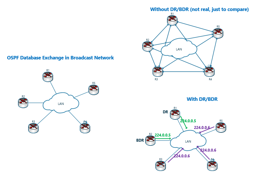
In addition, the database exchange between neighboring routers in the broadcast network is done through DR router and not one-to-one between every two neighboring routers.
The multicast address 224.0.0.6 is reserved for DR router. All routers on the broadcast network send database information to DR only (by sending to the address 224.0.0.6) and DR router is responsible for advertising database information to all neighboring routers on the broadcast network (by sending to the address 224.0.0.5). And in this way, the database information is advertised indirectly between all the routers of the broadcast network.
To ensure the correct operation of OSPF in the broadcast network, there is another router called BDR, which, in addition to DR, also listens to the multicast address 224.0.0.6 as a backup, and if the DR router fails, BDR replaces DR and a new BDR will be selected.
ISIS in Broadcast Network
In ISIS protocol there is also a router called DIS (Designated IS), whose naming similarity with DR conveys the idea of the same functionality of DR and DIS, but the fact is that there are also some differences between them.
With ISIS, like OSPF, a router named DIS is elected in broadcast networks, but unlike OSPF, there is no backup router with the name of BDIS, and there is in principle no need for such a router. Why?!
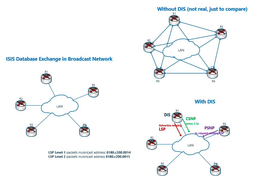
In ISIS there is no special multicast address for DIS router. If you remember, ISIS packets are encapsulated directly on data link layer and all ISIS LSP Level 1 packets are advertised to MAC address 0180.c200.0014 and LSP Level 2 packets to MAC address 0180.c200.0015.
The DIS router helps to unify the database of broadcast network routers in different ways.
The DIS router sends the CSNP packet containing the list of database information every 10 seconds. The timer is also configurable. Each of the routers within the broadcast network, upon receiving the CSNP packet, compares the information to its own database. One of the following three situations occurs:
- If the CSNP information is the same with router’s database information, the router does not take any action because it means that the router’s database is up to date.
- If the information in the router’s database is not up-to-date, that router sends a request for LSP information that is not present in its own database by sending PSNP. The lower sequence number indicates that the LSP is not up-to-date.
- If the DIS router’s LSP sequence number is smaller than any of the routers in the broadcast network, the router with the higher sequence number send the LSP and updates the DIS database information.
Therefore, the DIS router helps routers ensure their database is up to date by regularly sending the list of database information, and if the database information of any of the broadcast network routers or the DIS router is not up to date, they will update each other by sending LSP.
ISIS LSP Acknowledgement in Broadcast network
If you remember, in Point-to-Point networks, after sending LSP, routers acknowledge each other by sending PSNP packet.
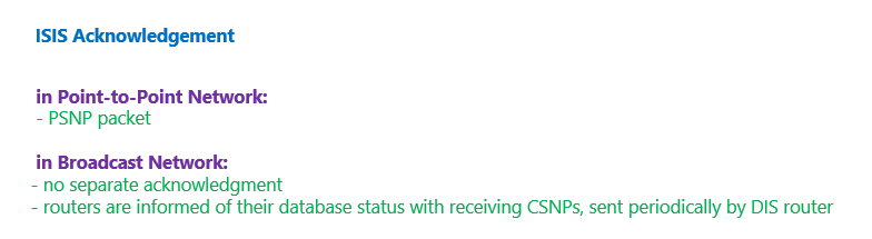
In broadcast networks, no separate acknowledgment is sent from either routers or DIS router, but routers are informed of their database status with receiving CSNPs, sent periodically by DIS router.
If any of the routers on the broadcast network have an out-of-date database, they request it by sending PSNP.
If database of DIS router’s is not up-to-date, normal router on the broadcast network will send an LSP to update the DIS router’s database.
DIS Election Process is ISIS
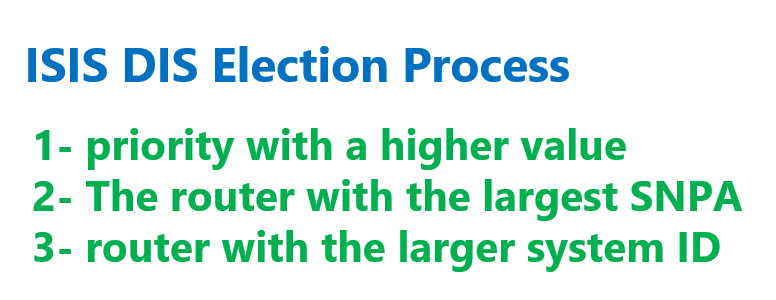
The question is, how is DIS router selected in the broadcast network? To select DIS, the following steps are performed in order:
1- A router whose interface priority has a higher value in the broadcast network.
The range of priority on the interface is from 0 to 127 and all values are valid. This is unlike OSPF protocol where a value of zero in the priority means that the router should not be DR or BDR.
We use the “isis priority” command to configure the priority.
interface Ethernet0/0
 isis priority 100 level-1
As you can see, the priority value can be configured separately for level 1 and level 2- The router with the largest SNPA.
If you remember, SNPA address in CLNS network is a layer 2 address tied to each interface.
For Ethernet, SNPA it is the MAC address of the interface and for Frame Relay and ATM networks it is the value of DLCI and VPI/VCI.
3- Since routers in Frame Relay and ATM networks can have the same DLCI or VPI/VCI address, the router with the larger system ID takes on the role of the DIS in the next step.
DIS election in ISIS, unlike DR in OSPF, is pre-emptive. This means that any router with better conditions can take over the role of DIS at any time.
Backup DIS in ISIS in Broadcast Network
In ISIS, there is no backup DIS concept because as mentioned earlier, DIS router does not have the central role of sending database information between routers in the broadcast network, and only by regularly sending the list of database information helps the routers to ensure that their database information is up-to-date.

At any time, any router can play the role of DIS. The DIS router announces its health by periodically sending hello every 3.3 seconds (one third of the hello time) and if no hello is received from it during the hello time, another router will immediately replace the DIS.
Pseudonode LSP in Broadcast Network
But DIS router plays another important role, similar to OSPF. The DIS router is responsible for sending the broadcast network topology to other routers. Otherwise, each router on the broadcast network must advertise its connection to each of the routers on the same broadcast network using a separate TLV. It requires each router to send (n-1) TLVs and a total of n(n-1) TLVs.
But in ISIS protocol, DIS router sends a pseudonode LSP to introduce all routers of the broadcast network, and each router in this network only sends a TLV within the LSP pointing to the pseudonode LSP.
In the figure, on the left, six routers are shown that are connected to a broadcast network.
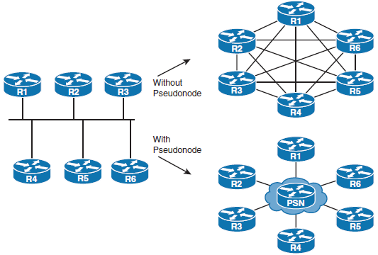
on the top right of the figure you see if each router wants to show its connection to other routers in the network, a high number of TLVs must be sent, which turns the topology into a full-mesh connection between all routers in the broadcast network.
The right and bottom part of the figure shows the real operation of ISIS where DIS router transmits broadcast network topology. The number of TLVs sent by the DIS router corresponds to the number of routers connected in the broadcast network.
The information that is transmitted by the DIS router and shows the topology of the broadcast network is called Pseudonode LSP.
Each of the other routers in the broadcast network sends only one TLV, which indicates the connection to the broadcast network.
Therefore, in broadcast networks, there is an additional LSP named Pseudonode LSP. This LSP is in addition to the Router LSP that each router sends separately.
Pseudonode LSP is sent by the DIS router.
System-id and Pseudonode-id in Broadcast Network
It is reminded that each LSP is identified by system-id, Pseudonode-id and LSP Fragment Number.
Also, remember that each router address its interfaces through a single byte called Circuit ID.
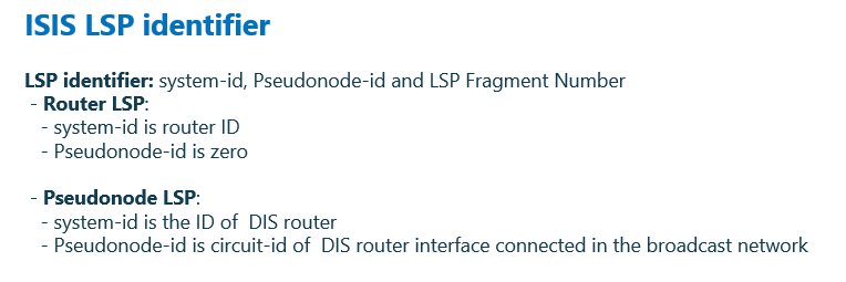
In Router LSP, the system-id value is the same as the router ID and the Pseudonode-id value is zero, but in Pseudonode LSP which is advertised by DIS, the system-id value is the ID of the DIS router and the Pseudonode-id is also the circuit-id of the DIS router interface connected in the broadcast network.
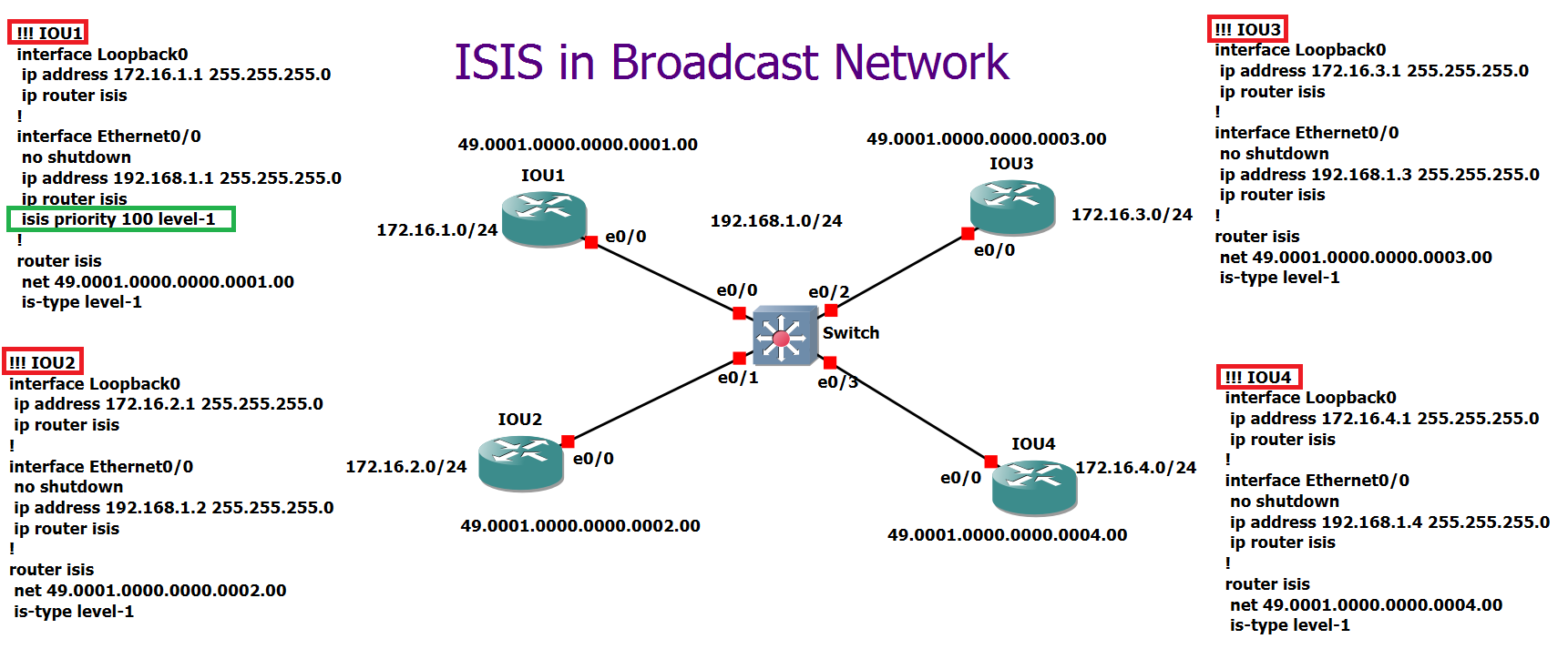
ISIS in Broadcast Network: Configuration Example
To better understand the database exchange process in broadcast networks and psudonode LSP in ISIS protocol, we configure ISIS in this topology and examine the result.
In this topology, there are four routers IOU1 to IOU4 are connected to each other through the broadcast network and all are in the same subnet 192.168.1.0/24.
A loopback interface is configured for each router in the range 172.16.x.0/24, in which the third octet is router number.
NET address are configured in the area 1(one) and with system-id equal to router number.
Interface connected to router IOU1 is configured with a higher priority with “isis priority” command in interface context. This is to force router IOU1 to be DIS.
!!! IOU1
interface Loopback0
 ip address 172.16.1.1 255.255.255.0
 ip router isis
!
interface Ethernet0/0
 no shutdown
 ip address 192.168.1.1 255.255.255.0
 ip router isis
 isis priority 100 level-1
!
router isis
 net 49.0001.0000.0000.0001.00
 is-type level-1

!!! IOU2
interface Loopback0
 ip address 172.16.2.1 255.255.255.0
 ip router isis
!
interface Ethernet0/0
 no shutdown
 ip address 192.168.1.2 255.255.255.0
 ip router isis
!
router isis
 net 49.0001.0000.0000.0002.00
 is-type level-1


!!! IOU3
interface Loopback0
 ip address 172.16.3.1 255.255.255.0
 ip router isis
!
interface Ethernet0/0
 no shutdown
 ip address 192.168.1.3 255.255.255.0
 ip router isis
!
router isis
 net 49.0001.0000.0000.0003.00
 is-type level-1


!!! IOU4
interface Loopback0
 ip address 172.16.4.1 255.255.255.0
 ip router isis
!
interface Ethernet0/0
 no shutdown
 ip address 192.168.1.4 255.255.255.0
 ip router isis
!
router isis
 net 49.0001.0000.0000.0004.00
 is-type level-1
In the first step, we use “show isis hostname” command to check the list of routers, the value of the system ID, and the corresponding hostname.
IOU1#show isis hostname
Level  System ID      Dynamic Hostname  (notag)
     * 0000.0000.0001 IOU1
 1     0000.0000.0002 IOU2
 1     0000.0000.0003 IOU3
 1     0000.0000.0004 IOU4
IOU1#
We also use the “show isis neighbors” command in router IOU1 to list the neighbors.
IOU1#show isis neighbors

System Id      Type Interface   IP Address      State Holdtime Circuit Id
IOU2           L1   Et0/0       192.168.1.2     UP    24       IOU1.01
IOU3           L1   Et0/0       192.168.1.3     UP    24       IOU1.01
IOU4           L1   Et0/0       192.168.1.4     UP    26       IOU1.01
IOU1#
As you can see, router IOU1 has three neighbors IOU2 to IOU4, but the circuit-id of all neighboring routers in the broadcast network is equal to the circuit-id value of the DIS router. In this topology, the router IOU1 is DIS router.
The command “show isis neighbors details” shows SNPA address as well as the Priority value of each router.
IOU1#show isis neighbors detail

System Id      Type Interface   IP Address      State Holdtime Circuit Id
IOU2           L1   Et0/0       192.168.1.2     UP    25       IOU1.01
  Area Address(es): 49.0001
  SNPA: aabb.cc00.0200
  State Changed: 00:00:38
  LAN Priority: 64
  Format: Phase V
  Remote TID: 0
  Local TID:  0
  Interface name: Ethernet0/0
IOU3           L1   Et0/0       192.168.1.3     UP    24       IOU1.01
  Area Address(es): 49.0001
  SNPA: aabb.cc00.0300
  State Changed: 00:00:38
  LAN Priority: 64
  Format: Phase V
  Remote TID: 0
  Local TID:  0
  Interface name: Ethernet0/0
IOU4           L1   Et0/0       192.168.1.4     UP    25       IOU1.01
  Area Address(es): 49.0001
  SNPA: aabb.cc00.0400
  State Changed: 00:00:38
  LAN Priority: 64
System Id      Type Interface   IP Address      State Holdtime Circuit Id
  Format: Phase V
  Remote TID: 0
  Local TID:  0
  Interface name: Ethernet0/0
IOU1#
Using “show clns interface” command on IOU1 router, you can see that the priority value of the IOU1 router is 100 and that is the reason why this router is selected as DIS.
IOU1#show clns interface
Ethernet0/0 is up, line protocol is up
  Checksums enabled, MTU 1497, Encapsulation SAP
  ERPDUs enabled, min. interval 10 msec.
  CLNS fast switching disabled
  CLNS SSE switching disabled
  DEC compatibility mode OFF for this interface
  Next ESH/ISH in 26 seconds
  Routing Protocol: IS-IS
    Circuit Type: level-1-2
    Interface number 0x1, local circuit ID 0x1
    Level-1 Metric: 10, Priority: 100, Circuit ID: IOU1.01
    DR ID: IOU1.01
    Level-1 IPv6 Metric: 10
    Number of active level-1 adjacencies: 3
    Next IS-IS LAN Level-1 Hello in 1 seconds
Ethernet0/1 is administratively down, line protocol is down
  CLNS protocol processing disabled
...
Loopback0 is up, line protocol is up
  Checksums enabled, MTU 1514, Encapsulation LOOPBACK
  ERPDUs enabled, min. interval 10 msec.
  CLNS fast switching disabled
  CLNS SSE switching disabled
  DEC compatibility mode OFF for this interface
  Next ESH/ISH in 28 seconds
  Routing Protocol: IS-IS
    Circuit Type: level-1-2
    Interface number 0x0, local circuit ID 0x100
    Level-1 Metric: 10, Priority: 64, Circuit ID: IOU1.00
    Level-1 IPv6 Metric: 10
    Number of active level-1 adjacencies: 0
    Next IS-IS Hello in 3 seconds
    if state DOWN
IOU1#
By using the command “show isis database“, you can see the summary of the router IOU1 database table.
IOU1#show isis database

IS-IS Level-1 Link State Database:
LSPID                 LSP Seq Num  LSP Checksum  LSP Holdtime      ATT/P/OL
IOU1.00-00          * 0x00000003   0x9E53        1128              0/0/0
IOU1.01-00          * 0x00000001   0x9E95        1128              0/0/0
IOU2.00-00            0x00000003   0xDA13        1126              0/0/0
IOU3.00-00            0x00000003   0x17D2        1126              0/0/0
IOU4.00-00            0x00000003   0x5392        1126              0/0/0
IOU1#
As you can see, there are five LSPs in router IOU1. Each router has sent one Router LSP and one is Pseudonode LSP sent by the DIS router.
The Pseudonode Id of all Router LSPs are zero, except for the Pseudonode LSP whose Pseudonode Id is equal to the Circuit-Id of DIS router.
In this scenario, the Pseudonode Id of the psudonode LSP sent by DIS router is 0x01. Fragment number of all LSPs is zero because only one packet is sent for each LSP.
To view the LSP details on the IOU1 router, we use the “show isis database detail” command.
IOU1#show isis database detail

IS-IS Level-1 Link State Database:
LSPID                 LSP Seq Num  LSP Checksum  LSP Holdtime      ATT/P/OL
IOU1.00-00          * 0x00000003   0x9E53        1114              0/0/0
  Area Address: 49.0001
  NLPID:        0xCC
  Hostname: IOU1
  IP Address:   172.16.1.1
  Metric: 10         IP 172.16.1.0 255.255.255.0
  Metric: 10         IP 192.168.1.0 255.255.255.0
  Metric: 10         IS IOU1.01
IOU1.01-00          * 0x00000001   0x9E95        1115              0/0/0
  Metric: 0          IS IOU1.00
  Metric: 0          IS IOU2.00
  Metric: 0          IS IOU3.00
  Metric: 0          IS IOU4.00
IOU2.00-00            0x00000003   0xDA13        1112              0/0/0
  Area Address: 49.0001
  NLPID:        0xCC
  Hostname: IOU2
  IP Address:   172.16.2.1
  Metric: 10         IP 172.16.2.0 255.255.255.0
  Metric: 10         IP 192.168.1.0 255.255.255.0
  Metric: 10         IS IOU1.01
IOU3.00-00            0x00000003   0x17D2        1112              0/0/0
  Area Address: 49.0001
  NLPID:        0xCC
  Hostname: IOU3
  IP Address:   172.16.3.1
  Metric: 10         IP 172.16.3.0 255.255.255.0
  Metric: 10         IP 192.168.1.0 255.255.255.0
  Metric: 10         IS IOU1.01
IOU4.00-00            0x00000003   0x5392        1112              0/0/0
  Area Address: 49.0001
  NLPID:        0xCC
  Hostname: IOU4
  IP Address:   172.16.4.1
  Metric: 10         IP 172.16.4.0 255.255.255.0
  Metric: 10         IP 192.168.1.0 255.255.255.0
  Metric: 10         IS IOU1.01
IOU1#
As you can see, all routers have sent the network 192.168.1.0/24 in advertising LSP.
Also, all routers announce their connection to the broadcast network by sending a common TLV of IS type that points to the Pseudonode LSP.
The pseudonode LSP is IOU1.01 which is sent by DIS router, IOU1, showing the list of routers in the broadcast network.
Summary of DIS and Pseudonode LSP in ISIS
To summarize, it is emphasized again that the DIS router reduces its hello time and hold time to one third of the configured timers, so that the failure of the DIS router is recognized by other routers faster.
If the DIS router is disconnected, another router is selected as the DIS router without the need to make changes in the adjacency.
The change of DIS is done only by sending a new Pseudonode LSP by the new DIS router. All routers also update their LSP to point to the new Pseudonode LSP. The relative simplicity of this process is the main reason for not having Backup DIS in the ISIS protocol.