Carrier Supporting Carrier (CSC) in MPLS VPN occurs when a service provider uses another provider’s MPLS VPN to connect its own sites. The larger provider offering the MPLS VPN is the backbone carrier, while the smaller provider serving end customers is the customer carrier.
Carrier Supporting Carriers (CSC) Fundamental
As mentioned, Carrier Supporting Carrier (CSC) in MPLS VPN solutions is used when a service provider that delivers MPLS VPN services to end customers relies on the MPLS VPN infrastructure of another service provider for its own transport connectivity.
In this model, the service provider that directly offers VPN services to end customers is referred to as the customer carrier, while the service provider that provides the underlying MPLS VPN transport infrastructure is known as the backbone carrier.
In this lesson, we will examine how the control plane and data plane operate in a Carrier Supporting Carrier (CSC) environment through a demonstration example.
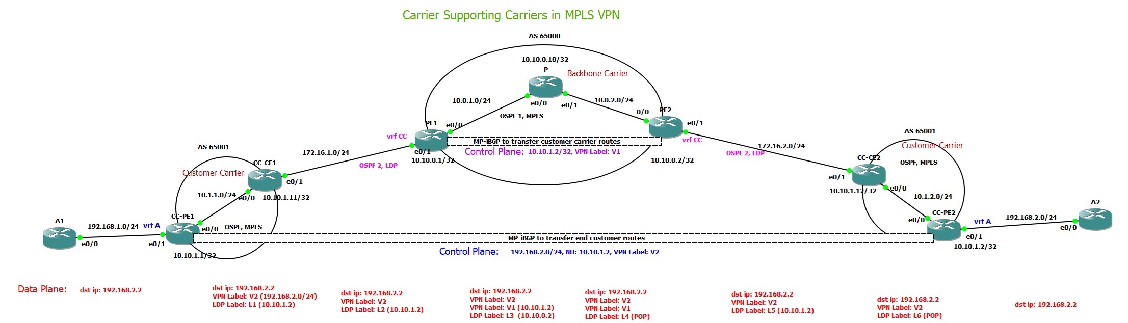
In this example, a backbone carrier with AS number 65000 provides MPLS VPN services to another MPLS VPN service provider, known as the customer carrier, with AS number 65001. The customer carrier connects two sites belonging to end customer A, namely A1 and A2, through its POP locations.
The objective of this setup is to establish end-to-end connectivity between A1 and A2 using an MPLS VPN service, while focusing on how the control plane and data plane operate to enable this connectivity.

To enable this connectivity, the first step is to establish connectivity between the customer carrier sites across the backbone carrier’s MPLS VPN infrastructure. There is nothing special about this step; a standard MPLS VPN configuration is used.
The key point to note in this example is that OSPF is configured between the backbone carrier and the customer carrier to advertise the required customer carrier routes to the backbone carrier PE routers.
On the backbone carrier PE routers, the interfaces connecting to the customer carrier are assigned to a dedicated VRF named “cc”, which represents the customer carrier.
Within the backbone carrier PE routers, two separate OSPF processes are running: OSPF process 1 is used for routing within the backbone carrier core. OSPF process 2 runs inside the VRF “cc” and is used to exchange routing information between the backbone carrier and the customer carrier.
In addition, MP-BGP with the VPNv4 address family is configured between the backbone carrier PE routers to advertise customer carrier routes across the backbone carrier network.
With this setup, it is essential to ensure end-to-end connectivity between the customer carrier sites, particularly between the loopback interfaces of CC-PE1 (10.10.1.1) and CC-PE2 (10.10.1.2), as these loopbacks are used for control-plane communication.
Now we can focus on the connectivity between A1 and A2. The end-customer routes are advertised between CC-PE1 and CC-PE2 using MP-BGP with the VPNv4 address family, and connectivity between these customer carrier PE routers has already been verified through the backbone carrier network.
However, to achieve end-to-end MPLS forwarding, it is necessary to ensure that an end-to-end Label Switched Path (LSP) exists between the customer carrier PE routers.
To accomplish this, labels must be assigned to the loopback interface addresses of the customer carrier PE routers across the entire path. This requires enabling LDP between the backbone carrier and the customer carrier, ensuring that label distribution occurs end to end and that a continuous LSP is established between CC-PE1 and CC-PE2.
CSC Configuration Example
Here, I have shown the most important configuration sections of the topology, including the backbone carrier PE router and the customer carrier PE and CE routers.
On the backbone carrier PE routers, a VRF named "cc" is configured, and the interface connecting the backbone carrier to the customer carrier is assigned to this VRF.
Two OSPF processes are configured on the backbone carrier PE routers. One OSPF process is used for routing within the backbone carrier core. A second OSPF process runs within the "cc" VRF and is used for routing between the customer carrier and the backbone carrier.
MPLS is enabled not only within the backbone carrier core but also on the link between the backbone carrier and the customer carrier.
In addition, BGP with the VPNv4 address family is configured between the backbone carrier PE routers to exchange customer carrier routing information
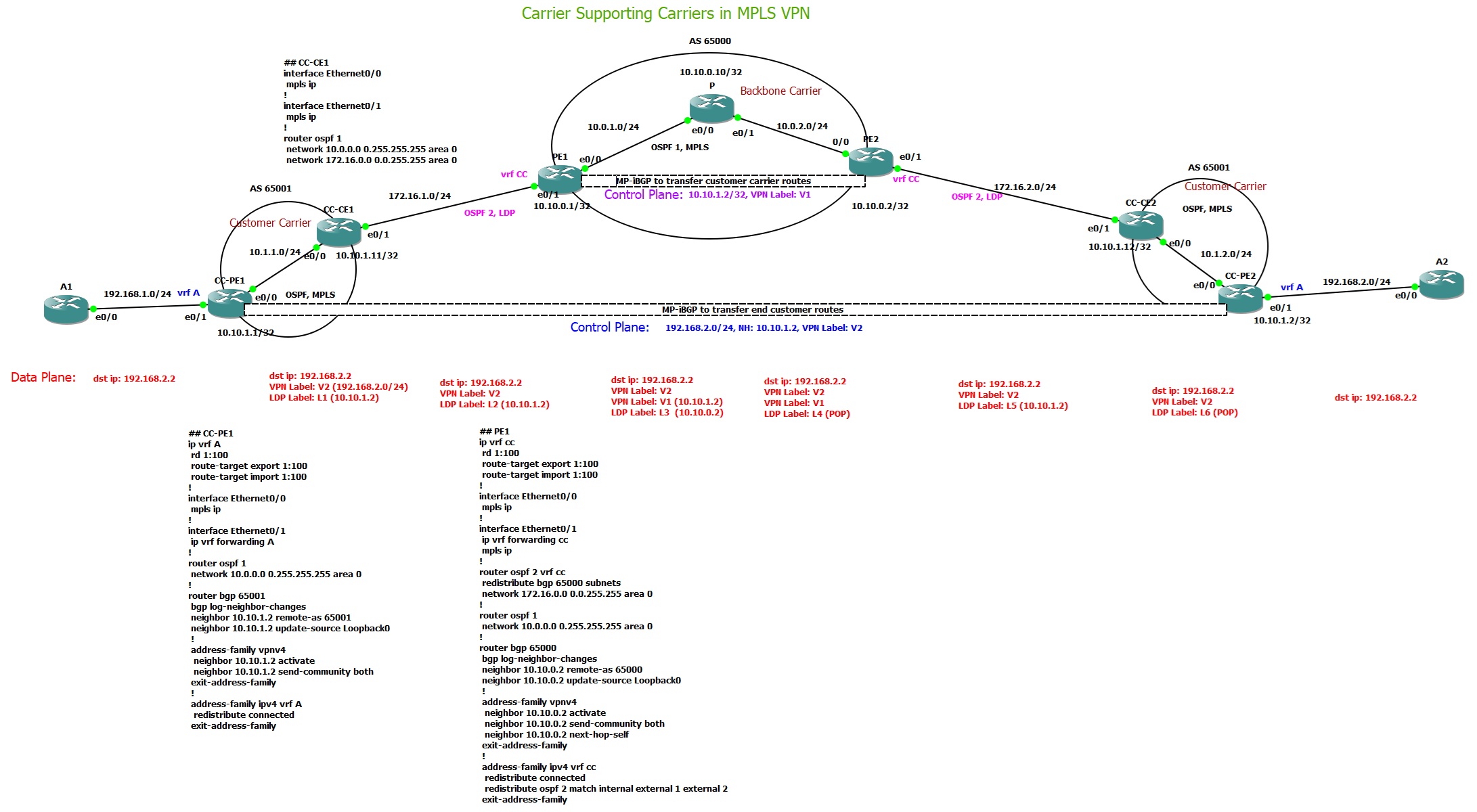
## PE1
ip vrf cc
 rd 1:100
 route-target export 1:100
 route-target import 1:100
!
ip cef
!
mpls label protocol ldp
!
interface Loopback0
 ip address 10.10.0.1 255.255.255.255
!
interface Ethernet0/0
 ip address 10.0.1.2 255.255.255.0
 mpls ip
!
interface Ethernet0/1
 ip vrf forwarding cc
 ip address 172.16.1.1 255.255.255.0
 mpls ip
!
router ospf 2 vrf cc
 redistribute bgp 65000 subnets
 network 172.16.0.0 0.0.255.255 area 0
!
router ospf 1
 network 10.0.0.0 0.255.255.255 area 0
!
router bgp 65000
 bgp log-neighbor-changes
 neighbor 10.10.0.2 remote-as 65000
 neighbor 10.10.0.2 update-source Loopback0
 !
 address-family vpnv4
  neighbor 10.10.0.2 activate
  neighbor 10.10.0.2 send-community both
  neighbor 10.10.0.2 next-hop-self
 exit-address-family
 !
 address-family ipv4 vrf cc
  redistribute connected
  redistribute ospf 2 match internal external 1 external 2
 exit-address-family
!
mpls ldp router-id Loopback0
On the customer carrier CE router that is connected to the backbone carrier, the key requirements are that OSPF and LDP are enabled on the link between the customer carrier and the backbone carrier.
In this example, the OSPF process used on this link is the same OSPF process used internally within the customer carrier network. However, it could also be a separate OSPF process, or even a different routing protocol altogether, in order to provide better isolation and operational control.
## CC-CE1
ip cef
!
mpls label protocol ldp
!
interface Loopback0
 ip address 10.10.1.11 255.255.255.255
!
interface Ethernet0/0
 ip address 10.1.1.1 255.255.255.0
 mpls ip
!
interface Ethernet0/1
 ip address 172.16.1.2 255.255.255.0
 mpls ip
!
router ospf 1
 network 10.0.0.0 0.255.255.255 area 0
 network 172.16.0.0 0.0.255.255 area 0
!
mpls ldp router-id Loopback0
Finally, the configuration of the customer carrier PE router that connects to end customers follows the standard MPLS VPN PE design. This includes running OSPF and LDP, as well as advertising customer routes via BGP using the VPNv4 address family between PE routers
## CC-PE1
ip vrf A
 rd 1:100
 route-target export 1:100
 route-target import 1:100
!
ip cef
!
mpls label protocol ldp
!
interface Loopback0
 ip address 10.10.1.1 255.255.255.255
!
interface Ethernet0/0
 ip address 10.1.1.2 255.255.255.0
 mpls ip
!
interface Ethernet0/1
 ip vrf forwarding A
 ip address 192.168.1.1 255.255.255.0
!
router ospf 1
 network 10.0.0.0 0.255.255.255 area 0
!
router bgp 65001
 bgp log-neighbor-changes
 neighbor 10.10.1.2 remote-as 65001
 neighbor 10.10.1.2 update-source Loopback0
 !
 address-family vpnv4
  neighbor 10.10.1.2 activate
  neighbor 10.10.1.2 send-community both
 exit-address-family
 !
 address-family ipv4 vrf A
  redistribute connected
 exit-address-family
!
mpls ldp router-id Loopback0
Control Plane Verification in a CSC Solution
To verify correct control plane operation in a CSC solution, we first validate routing and label information for connectivity between the customer carrier PE routers across the backbone carrier network. This ensures that the customer carrier infrastructure is properly transported over the backbone carrier MPLS core.
Next, we verify routing and label distribution for end-customer connectivity across the customer carrier network, confirming that customer routes are correctly learned, labeled, and advertised through the customer carrier PE routers
On the backbone carrier PE1 router, we can see the route learned to reach the customer carrier CC-PE2 loopback interface (10.10.1.2) via backbone carrier PE2, with an associated VPN label 24.
PE1#show bgp vpnv4 unicast all labels
   Network          Next Hop      In label/Out label
Route Distinguisher: 1:100 (cc)
...
   10.10.1.2/32     10.10.0.2       nolabel/24
...
On the customer carrier CC-PE1 router, we can see the route learned to reach end customer A2 (192.168.2.0/24) via customer carrier CC-PE2, with an associated VPN label 22
CC-PE1#show bgp vpnv4 unicast all labels
   Network          Next Hop      In label/Out label
Route Distinguisher: 1:100 (A)
...
   192.168.2.0      10.10.1.2       nolabel/22
These two VPN labels play a crucial role in the data plane, as they enable proper label stacking and establish the end-to-end connectivity between the end-customer sites
Data Plane Verification in a CSC Solution
To verify data plane operation, we first check connectivity between the customer carrier PE routers across the backbone carrier network, including the label stack used for forwarding. In particular, we must confirm that the VPN label advertised by backbone carrier PE2 is correctly applied for connectivity from CC-PE1 to the CC-PE2 loopback interface.
Additionally, we must ensure that a complete end-to-end LSP exists between the customer carrier PE routers, as this is essential for maintaining connectivity between the end-customer sites.
For connectivity from CC-PE1 to the CC-PE2 loopback interface, we can verify both expectations:
An end-to-end LSP exists across the backbone carrier without label popping or breaking.
The VPN label 24 is correctly used as the inner label, exactly as advertised by PE2 to PE1 over the backbone carrier using the BGP VPNv4 address family.
CC-PE1#traceroute 10.10.1.2 source 10.10.1.1
Type escape sequence to abort.
Tracing the route to 10.10.1.2
VRF info: (vrf in name/id, vrf out name/id)
  1 10.1.1.1 [MPLS: Label 20 Exp 0] 8 msec 10 msec 10 msec
  2 172.16.1.1 [MPLS: Label 28 Exp 0] 8 msec 9 msec 8 msec
  3 10.0.1.1 [MPLS: Labels 17/24 Exp 0] 9 msec 7 msec 2 msec
  4 172.16.2.1 [MPLS: Label 24 Exp 0] 3 msec 6 msec 2 msec
  5 172.16.2.2 [MPLS: Label 20 Exp 0] 1 msec 1 msec 5 msec
  6 10.1.2.2 5 msec 7 msec 4 msec
CC-PE1#
For end-customer site connectivity, specifically from A1 to A2, there are two important points to note.
First, we observe VPN label 22 used as the inner label for the destination 192.168.2.0/24, which is advertised from CC-PE2 to CC-PE1 in the control plane via the BGP VPNv4 address family.
Second, this is the only scenario in the entire topology where traffic traverses the backbone carrier network with three labels in the label stack:
The outer label is an LDP label, used to forward traffic across the backbone carrier core.
The middle label is a VPN label assigned to CC-PE2 (the destination PE router in the customer carrier) and advertised by the destination PE router in the backbone carrier.
The inner label is a VPN label assigned to end customer A2, advertised by the destination PE router in the customer carrier.
This three-label stack is a key characteristic of CSC data plane forwarding, enabling full end-to-end VPN connectivity while preserving proper carrier separation.
A1#traceroute 192.168.2.2
Type escape sequence to abort.
Tracing the route to 192.168.2.2
VRF info: (vrf in name/id, vrf out name/id)
  1 192.168.1.1 6 msec 5 msec 5 msec
  2 10.1.1.1 [MPLS: Labels 20/22 Exp 0] 9 msec 8 msec 8 msec
  3 172.16.1.1 [MPLS: Labels 28/22 Exp 0] 3 msec 2 msec 2 msec
  4 10.0.1.1 [MPLS: Labels 17/24/22 Exp 0] 6 msec 2 msec 6 msec
  5 10.0.2.2 [MPLS: Labels 24/22 Exp 0] 2 msec 8 msec 3 msec
  6 172.16.2.2 [MPLS: Labels 20/22 Exp 0] 1 msec 1 msec 1 msec
  7 192.168.2.1 6 msec 3 msec 6 msec
  8 192.168.2.2 6 msec 7 msec 9 msec