5. segment routing protection concept
6. segment routing protection implementation and troubleshooting
What does traffic engineering mean? This means that at the edge of the network you can control the path of a particular traffic up to destination. For example, if there is congestion on the network and you want to ensure that quality of gold customers’ traffic is maintained, you control the path of gold customer traffic at the edge of the network in a way to get enough bandwidth or minimal delay.
Traffic engineering can be traditionally implemented in MPLS networks with RSVP-TE, but segment routing traffic engineering has many advantages. The traditional method requires you to enable RSVP-TE protocol, but in the segment routing network you do not need any other protocol for traffic engineering.
RSVP-TE maintains the state of all TE tunnels in the routers in the path, but segment routing does not maintain any state in any router but in the packet itself which is more scalable.
In RSVP-TE, tunnels have to be created manually but in SRTE, tunnels are created automatically.
There are a few other advantages in the Segment Routing Traffic Engineering that we will get to know in the next few videos.
To understand how traffic engineering works and how it is implemented in segment routing networks, I have already prepared a topology.
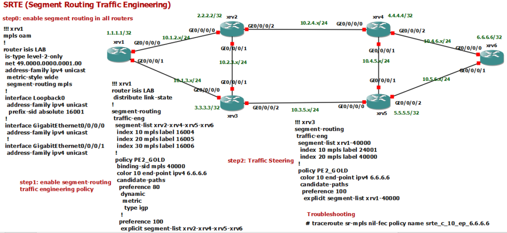
In this topology, routers xv1 and xrv6 are our edge routers. The addresses of the loopback interfaces range from 1.1.1.1 to 6.6.6.6 according to the router numbers. The subnet of the links between routers also depends on the router number. For example, 10.1.2.x is selected for the subnet between routers xrv1 and xrv2. The last digit of the IP address is also the router number.
Enable segment routing in ISIS
In step 0, segment routing is activated in all routers with the ISIS routing protocol. The configuration of the router xrv1 is shown here. ISIS is activated in all interfaces. With the command “segment-routing mpls” we activate the segment routing in ISIS. Prefix SID of loopback0 of all routers must also be configured, which I configured from 16001 in router xr1 to 16006 in router xrv6.
“mpls oam” is activated just for troubleshooting purposes or to ping and traceroute in MPLS data plane and it is not related to segment routing configuration.
RP/0/RP0/CPU0:xrv1#show runn mpls
Wed Jul  7 19:22:54.605 UTC
mpls oam
!

RP/0/RP0/CPU0:xrv1#show runn router isis
Wed Jul  7 19:23:00.558 UTC
router isis LAB
 is-type level-2-only
 net 49.0000.0000.0001.00
 distribute link-state
 address-family ipv4 unicast
  metric-style wide
  segment-routing mpls
 !
 interface Loopback0
  address-family ipv4 unicast
   prefix-sid absolute 16001
  !
 !
 interface GigabitEthernet0/0/0/0
  address-family ipv4 unicast
   metric 15
  !
 !
 interface GigabitEthernet0/0/0/1
  address-family ipv4 unicast
Enable Traffic Engineering using policy in segment routing network
In step 1, we implement traffic engineering using policy. In fact, traffic engineering is enabled using policy in the segment routing network.
RP/0/RP0/CPU0:xrv1#show runn segment-routing
Wed Jul  7 19:23:49.983 UTC
segment-routing
 traffic-eng
  segment-list xrv2-xrv4-xrv5-xrv6
   index 10 mpls label 16004
   index 20 mpls label 16005
   index 30 mpls label 16006
  !
  policy PE2_GOLD
   binding-sid mpls 40000
   color 10 end-point ipv4 6.6.6.6
   candidate-paths
    preference 80
     dynamic
      metric
       type igp
      !
     !
    !
    preference 100
     explicit segment-list xrv2-xrv4-xrv5-xrv6
For example, if you want gold customer’s traffic which have paid more money to be routed to a specific path with minimal delay and silver customer’s traffic which have paid less to a default IGP path. to implement this, you need to define two policies. One for gold and one for silver customers.
A policy in a router is uniquely identified by its destination address and color. Color is to differentiate our services. for example color 10 is for gold customers and color 20 is for silver customers.
To implement a policy, in “segment routing traffic engineering” context, we define a policy. Here I have configured a policy with the name of PE2_GOLD. we make a policy to be unique by configuring destination address and color. Here the destination address is 6.6.6.6 and color is 10 which is used for gold customers.
A binding-SID must be configured statically or dynamically for each policy, which I will explain in a few minutes.
There must be at least one candidate path for each policy. Every path has a preference. Higher preference has higher priority. The path can be computed dynamically with your given constraint to optimize IGP metric or delay and many other constraints or can be configured explicitly.
Here we have defined two paths. The explicit path has a higher preference. if it is not valid or available, the second path with lower preference is chosen, which is dynamic and is chosen according to best IGP path.
The explicit path is defined by a segment list named xrv2-xrv4-xrv5-xrv6, which is also our configured path. The explicit path is defined with a list of segment routing labels 16004, 16005 and then 16006. So the traffic will be routed first to xrv4 then xrv5 and then xrv6.
For traffic engineering to works we enable “distribute link-state” under ISIS/OSPF to feed the SRTE DB on the head-end.
router isis LAB

 distribute link-state
A binding-SID is assigned dynamically or manually for each policy and the selected active path. Here the binding-SID is configured manually as 40000. When we insert the binding-SID to the packet, it is automatically mapped to the the corresponding segment list of the active path of the policy, which here is 16004-16605-16006.
With “show mpls forwarding” you can see that incoming Binding-SID is mapped to outgoing label defined in segment routing traffic engineering policy.
RP/0/RP0/CPU0:xrv1#show mpls forwarding
Wed Jul  7 19:50:18.224 UTC
Local  Outgoing    Prefix             Outgoing     Next Hop        Bytes
Label  Label       or ID              Interface                    Switched
------ ----------- ------------------ ------------ --------------- ------------
16002  Pop         SR Pfx (idx 2)     Gi0/0/0/0    10.1.2.2        0
16003  Pop         SR Pfx (idx 3)     Gi0/0/0/1    10.1.3.3        0
16004  16004       SR Pfx (idx 4)     Gi0/0/0/0    10.1.2.2        0
16005  16005       SR Pfx (idx 5)     Gi0/0/0/1    10.1.3.3        0
16006  16006       SR Pfx (idx 6)     Gi0/0/0/1    10.1.3.3        504
24001  Pop         SR Adj (idx 1)     Gi0/0/0/0    10.1.2.2        0
24002  Pop         SR Adj (idx 3)     Gi0/0/0/0    10.1.2.2        0
24003  Pop         SR Adj (idx 1)     Gi0/0/0/1    10.1.3.3        0
24004  Pop         SR Adj (idx 3)     Gi0/0/0/1    10.1.3.3        0
24005  Pop         SR Adj (idx 0)     Gi0/0/0/0    10.1.2.2        0
24006  16004       SR TE: 1 [TE-INT]  Gi0/0/0/0    10.1.2.2        532
40000  Pop         No ID              srte_c_10_ep point2point     532
Binding-SID helps us with scalability. Instead of inserting 3 segments, we are only inserting one segment, 40000, pointing to the same path.
Another use of the binding-SID is to steer traffic through the traffic engineering path. That is, when router xrv1 receives a packet with segment 40000, then it will be steered through segment-list binding to 40000, which is 16004-16005-16006.
Steering Traffic in Traffic Engineering path in segment routing
In the next step we learn how to steer the traffic with Binding-SID. In the next videos, we will learn other automatic way of routing traffic through a traffic engineering path.
Step 2 is to better understand the binding-SID. In this step, we define a policy in the xrv3 router and ask the router to route the traffic with destination xrv6 via the explicit path 24001-4000. 24001 is the adjacency-SID for the connection between xrv3-xrv1, which may be different for you as it is created dynamically. Label 4000 is the binding-SID of the active path in the PE2_GOLD policy defined in xrv1. The current active path of the policy is xrv2-xrv4-xrv5-xrv6. so router xrv3, in order to forward the traffic to xrv6, instead of using xrv5-xrv6 direct path, it selects xrv1-xrv2-xrv4-xrv5-xrv6 according to the defined policy. So you can see how we can steer traffic in a specific path using Binding-SID.
RP/0/RP0/CPU0:xrv3#show runn segment-routing
Wed Jul  7 19:51:42.583 UTC
segment-routing
 traffic-eng
  segment-list xrv1-40000
   index 10 mpls label 24001
   index 20 mpls label 40000
  !
  policy PE2_GOLD
   color 10 end-point ipv4 6.6.6.6
   candidate-paths
    preference 100
     explicit segment-list xrv1-40000
Monitoring and troubleshooting segment routing traffic Engineering
This is our first segment routing traffic engineering scenario, that the configurations is already done in routers.
With “show segment-routing traffic-eng policy”, you can see the active path and Binding-SID of the configured policy.
RP/0/RP0/CPU0:xrv1#show segment-routing traffic-eng policy
Wed Jul  7 19:52:57.971 UTC

SR-TE policy database
---------------------

Color: 10, End-point: 6.6.6.6
  Name: srte_c_10_ep_6.6.6.6
  Status:
    Admin: up  Operational: up for 22:57:36 (since Jul  6 20:55:21.443)
  Candidate-paths:
    Preference: 100 (configuration) (active)
      Name: PE2_GOLD
      Requested BSID: 40000
      Explicit: segment-list xrv2-xrv4-xrv5-xrv6 (valid)
        Weight: 1, Metric Type: TE
          16004 [Prefix-SID, 4.4.4.4]
          16005
          16006
    Preference: 80 (configuration)
      Name: PE2_GOLD
      Requested BSID: 40000
      Dynamic (invalid)
        Metric Type: IGP,   Path Accumulated Metric: 0
  Attributes:
    Binding SID: 40000
    Forward Class: Not Configured
    Steering BGP disabled: no
    IPv6 caps enable: yes
Now let’s traceroute the traffic in segment-routing MPLS with the command
RP/0/RP0/CPU0:xrv1#traceroute sr-mpls nil-fec policy name srte_c_10_ep_6.6.6.6
Wed Jul  7 19:53:50.129 UTC

Tracing MPLS Label Switched Path with Nil FEC for SR-TE Policy srte_c_10_ep_6.6.6.6, timeout is 2 seconds

Codes: '!' - success, 'Q' - request not sent, '.' - timeout,
  'L' - labeled output interface, 'B' - unlabeled output interface,
  'D' - DS Map mismatch, 'F' - no FEC mapping, 'f' - FEC mismatch,
  'M' - malformed request, 'm' - unsupported tlvs, 'N' - no rx label,
  'P' - no rx intf label prot, 'p' - premature termination of LSP,
  'R' - transit router, 'I' - unknown upstream index,
  'X' - unknown return code, 'x' - return code 0

Type escape sequence to abort.

  0 10.1.2.1 MRU 1500 [Labels: 16004/16005/16006/explicit-null Exp: 0/0/0/0]
L 1 10.1.2.2 MRU 1500 [Labels: implicit-null/16005/16006/explicit-null Exp: 0/0/0/0] 39 ms
L 2 10.2.4.4 MRU 1500 [Labels: implicit-null/16006/explicit-null Exp: 0/0/0] 62 ms
L 3 10.4.5.5 MRU 1500 [Labels: implicit-null/explicit-null Exp: 0/0] 85 ms
! 4 10.5.6.6 50 ms
RP/0/RP0/CPU0:xrv1#
The Nil-FEC LSP ping and traceroute operation are simply extension of regular MPLS ping and trace route. nil-fec add the labels specified in the policy to the packet generated with ping and traceroute command.
As you can see the traffic is routed through our traffic-engineering path defined in the policy.
Now we can use the same troubleshooting command in router xrv3 to make sure that it is routed through our specified path.
RP/0/RP0/CPU0:xrv3#show segment-routing traffic-eng policy
Wed Jul  7 19:55:18.157 UTC

SR-TE policy database
---------------------

Color: 10, End-point: 6.6.6.6
  Name: srte_c_10_ep_6.6.6.6
  Status:
    Admin: up  Operational: up for 23:17:38 (since Jul  6 20:37:40.153)
  Candidate-paths:
    Preference: 100 (configuration) (active)
      Name: PE2_GOLD
      Requested BSID: dynamic
      Explicit: segment-list xrv1-40000 (valid)
        Weight: 1, Metric Type: TE
          24001
          40000
  Attributes:
    Binding SID: 24009
    Forward Class: Not Configured
    Steering BGP disabled: no
    IPv6 caps enable: yes
As you see in the segment list, first label is 24001 which points to the link between xrv3-xrv1. Your label may be different since it is generated dynamically. With command “show isis adjacency detail”, you can check your own adjacency label.
RP/0/RP0/CPU0:xrv3# show isis adjacency detail
Wed Jul  7 19:55:56.499 UTC

IS-IS LAB Level-2 adjacencies:
System Id      Interface                SNPA           State Hold Changed  NSF IPv4 IPv6
                                                                               BFD  BFD
xrv1           Gi0/0/0/0                000c.29b1.d7b1 Up    8    1d04h    Yes None None
  Area Address:           49
  Neighbor IPv4 Address:  10.1.3.1*
  Adjacency SID:          24000
  Non-FRR Adjacency SID:  24001
  DIS Priority:           64
  Local Priority:         64
  Neighbor Priority:      64 (DIS)
  Topology:               IPv4 Unicast
...
Now with traceroute command you make sue if the path is as your desired path defined in the policy. As you can see, with the help of Binding-SID, we steer traffic in the path defined in the policy.
RP/0/RP0/CPU0:xrv3#traceroute sr-mpls nil-fec policy name srte_c_10_ep_6.6.6.6
Wed Jul  7 19:56:43.504 UTC

Tracing MPLS Label Switched Path with Nil FEC for SR-TE Policy srte_c_10_ep_6.6.6.6, timeout is 2 seconds

Codes: '!' - success, 'Q' - request not sent, '.' - timeout,
  'L' - labeled output interface, 'B' - unlabeled output interface,
  'D' - DS Map mismatch, 'F' - no FEC mapping, 'f' - FEC mismatch,
  'M' - malformed request, 'm' - unsupported tlvs, 'N' - no rx label,
  'P' - no rx intf label prot, 'p' - premature termination of LSP,
  'R' - transit router, 'I' - unknown upstream index,
  'X' - unknown return code, 'x' - return code 0

Type escape sequence to abort.

  0 10.1.3.3 MRU 1500 [Labels: 40000/explicit-null Exp: 0/0]
L 1 10.1.3.1 MRU 1500 [Labels: 16004/16005/16006/implicit-null/explicit-null Exp: 0/0/0/0/0] 43 ms
L 2 10.1.2.2 MRU 1500 [Labels: implicit-null/16005/16006/implicit-null/explicit-null Exp: 0/0/0/0/0] 93 ms
L 3 10.2.4.4 MRU 1500 [Labels: implicit-null/16006/implicit-null/explicit-null Exp: 0/0/0/0] 40 ms
L 4 10.4.5.5 MRU 1500 [Labels: implicit-null/implicit-null/explicit-null Exp: 0/0/0] 58 ms
! 5 10.5.6.6 38 ms
As you can see , traffic is first forwarded to router xrv1 and then to router xrv6 through the path defined in policy with binding-SID 40000.