what is segment routing ODN?
We already know that on segment routing networks, instead of creating tunnels for each destination PE, we create policy. for each destination PE and SLA (GOLD or SILVER) we need a separate policy.
Segment Routing Traffic Engineering Concept
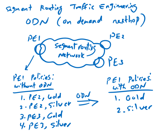
For example, suppose we have just two SLA in our network, GOLD and SILVER and we want to create policies in PE1 router then we have to create four policies. one Policy for GOLD customers and one Policy for SILVER customers behind PE2 router. Similar policies must also be configured for PE3 router.
Suppose we have 50 PE routers on our network, if we create two policies for each destination PE router, then we have to create 100 policies in each PE router. so we need around 5000 policies in our network.
With ODN, we only configure one policy for each SLA independent of destination PE router. If we have two SLAs, GOLD and SILVER, then we only create two policies in each PE router. If we have 50 PE routers in our network, with ODN, we need around 100 policies in our network, which is a lot less than 5000 policies without an ODN.
Suppose you write these two policies. route GOLD customer’s traffic through the best path with the lowest IGP metric and route the SILVER customer’s traffic through the best path with the lowest TE metric. Each SLA’s policy will be automatically duplicated for each destination PE that has customers with that SLA.
segment routing ODN Topology
This is the topology in which we want to implement and configure ODN. This is exact the topology that we have used in the last video. Just to recall, we have three PE routers, PE1, PE2 and PE3 with the IP addresses 1.1.1.1, 2.2.2.2 and 3.3.3.3 and two P routers, P1 and P2 with the IP addresses 11.11.11.11 and 12.12 .12.12.
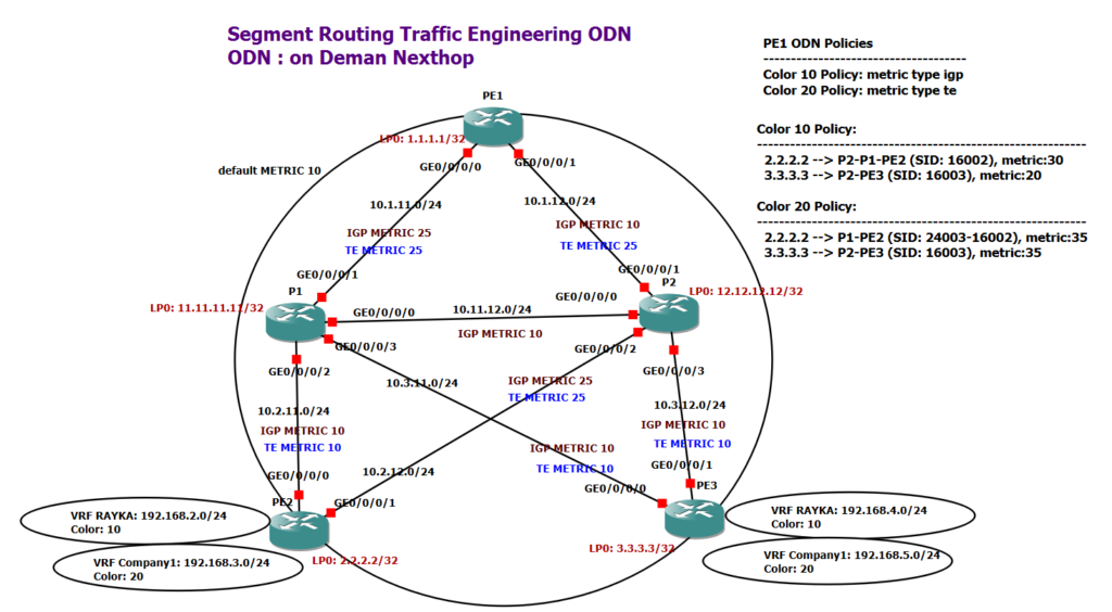
The IGP metric of all links are 10 by default in our topology and the TE metric is the same as the IGP metric by default. We change the IGP metric of the two links PE1-P1 and P2-PE2 to the value 25. Therefore, the TE metric of these two links is also automatically changed to 25. We also change the TE metric of the PE1-P2 link to 25, but the IGP metric of this link is still 10. IGP metric and TE metric of all other links are not changed and are 10 by default.
As I’ve shown here, I’ve only defined two policies in the PE1 router. One for GOLD customers with color 10 that dynamically routes traffic to the best IGP path and the other for SILVER customers with color 20 that routes traffic on the path with the lowest TE metric.
We have two customers in our network, RAYKA with GOLD SLA and Company1 with SILVER SLA, who are connected to both PE2 and PE3 routers. The prefixes 192.168.2.0/24 and 192.168.4.0/24 are for the customer RAYKA and the prefixes 192.168.3.0/24 and 192.168.5.0/24 belong to the customer of company1.
When we advertise customer routes on the network via BGP, the SLA color is also appended to the routes so that the PE1 router, receives routes from PE2 and PE3 with their corresponding SLA color.
PE1 receives routes for color 10 from both PE2 and PE3 routers. Therefore, with ODN, it duplicates our color 10 policy, once for the destination PE2 router and once for the destination PE3 router. PE1 similarly copies color 20 policy for both destination PE routers, PE2 and PE3. Therefore, four dynamic policies are created from our two ODN policies which is shown here.
The results of the individual Policies are also displayed here. For Gold customers with color 10 and behind PE2, the data traffic must be routed via the best IGP path. the best IGP path from PE1 to PE2 is PE1-P2-P1-PE2 with an IGP metric of 30 as we can see in the topology.
For Gold customers with color 10 and behind PE3, data traffic must also be routed through the best IGP path. the best IGP path from PE1 to PE3 is PE1-P2-PE3 with an IGP metric of 20 as we can see in the topology.
For SILVER customers with color 20 and behind PE2, data traffic must also be routed through the best path but with lowest TE metric. The best Path is PE1-P1-PE2 with TE metric of 35.
For SILVER customers with color 20 and behind PE3, data traffic must also be routed through the best path with lowest TE metric. The best Path is PE1-P2-PE3 with TE metric of 35.
Also, I’ve shown here which labels are added in each policy. In all policies, only the prefix-SID of the destination PE router is added since the best path is equal to the best IGP path. However, SILVER customers behind PE2 router use a different label stack because the best TE path differs from the best IGP path. in my topology, PE1 added two labels. First adjacency-SID 24003, which points to the connection between PE1-P1 and then the prefix-SID of PE2.
SR-TE ODN Configuration Example
For implementation of this scenario, all of the configurations are what we have already talked about. In this section we actually have two new configurations that are new to this video. First, how to set the TE metric, and second, how to implement ODN which are shown in red box.
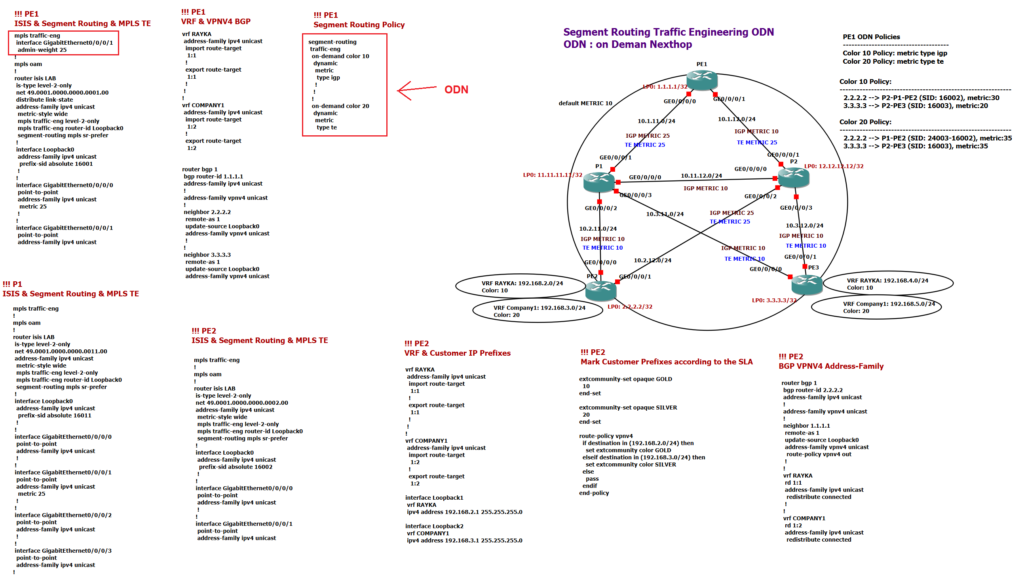
The configurations of PE1, P1 and PE2 are shown here. In PE1 router, IS-IS, MPLE TE and segment routing are configured in the same way as in the previous video. The only difference is in how the TE metric is configured. You can use the “admin-weight” command to configure a TE metric that differs from the IGP metric.
!!! PE1
mpls traffic-eng
 interface GigabitEthernet0/0/0/1
  admin-weight 25
!
mpls oam
!
router isis LAB
 is-type level-2-only
 net 49.0001.0000.0000.0001.00
 distribute link-state
 address-family ipv4 unicast
  metric-style wide
  mpls traffic-eng level-2-only
  mpls traffic-eng router-id Loopback0
  segment-routing mpls sr-prefer
 !
 interface Loopback0
  address-family ipv4 unicast
   prefix-sid absolute 16001
  !
 !
 interface GigabitEthernet0/0/0/0
  point-to-point
  address-family ipv4 unicast
   metric 25
  !
 !
 interface GigabitEthernet0/0/0/1
  point-to-point
  address-family ipv4 unicast
In this topology we need to configure VPNV4 BGP between PE routers to advertise customer routes. As you know, the routes are advertised with their SLA mark, which, depending on the customer’s SLA, they can be in color 10 (GOLD) or color 20 (SILVER).
!!! PE1
vrf RAYKA
 address-family ipv4 unicast
  import route-target
   1:1
  !
  export route-target
   1:1
  !
 !
!
vrf COMPANY1
 address-family ipv4 unicast
  import route-target
   1:2
  !
  export route-target
   1:2


router bgp 1
 bgp router-id 1.1.1.1
 address-family ipv4 unicast
 !
 address-family vpnv4 unicast
 !
 neighbor 2.2.2.2
  remote-as 1
  update-source Loopback0
  address-family vpnv4 unicast
  !
 !
 neighbor 3.3.3.3
  remote-as 1
  update-source Loopback0
  address-family vpnv4 unicast
I have configured VRF RAYKA with route-target 1: 1 and VRF COMPANY1 with route-target 1: 2. Then VPNV4 BGP neighborship with routers PE2 and PE3 are configured.
In the last part of PE1 configuration, the configuration of ODN or on demand policy is displayed. As you see, in ODN, policies are configured just according to the SLA, and destination PE router is not configured in ODN policy. The policy will be replicated for each destination PE router dynamically when required. We have two policies, GOLD, with color 10 which route traffic on the best IGP path and SILVER, with color 20 which route traffic on the best path with lowest TE metric.
!!! PE1
segment-routing
 traffic-eng
  on-demand color 10
   dynamic
    metric
     type igp
    !
   !
  !
  on-demand color 20
   dynamic
    metric
     type te
The configuration of the P1 router is also displayed here, but there is nothing new to explain. ISIS, MPLS TE, and segment routing configurations are exactly the same as what we have configured and explained in the last video.
!!! P1
mpls traffic-eng
!
mpls oam
!
router isis LAB
 is-type level-2-only
 net 49.0001.0000.0000.0011.00
 address-family ipv4 unicast
  metric-style wide
  mpls traffic-eng level-2-only
  mpls traffic-eng router-id Loopback0
  segment-routing mpls sr-prefer
 !
 interface Loopback0
  address-family ipv4 unicast
   prefix-sid absolute 16011
  !
 !
 interface GigabitEthernet0/0/0/0
  point-to-point
  address-family ipv4 unicast
  !
 !
 interface GigabitEthernet0/0/0/1
  point-to-point
  address-family ipv4 unicast
   metric 25
  !
 !
 interface GigabitEthernet0/0/0/2
  point-to-point
  address-family ipv4 unicast
  !
 !
 interface GigabitEthernet0/0/0/3
  point-to-point
  address-family ipv4 unicast
!
One of the most important configurations in PE routers is to send customer routes over the BGP VPNV4 address family with their SLA marking.
The configuration of the PE2 router is displayed here. First, ISIS, segment routing, and MPLS TE, which is the same as the PE1 router. There is nothing left to explain.
!!! PE2
mpls traffic-eng
!
mpls oam
!
router isis LAB
 is-type level-2-only
 net 49.0001.0000.0000.0002.00
 address-family ipv4 unicast
  metric-style wide
  mpls traffic-eng level-2-only
  mpls traffic-eng router-id Loopback0
  segment-routing mpls sr-prefer
 !
 interface Loopback0
  address-family ipv4 unicast
   prefix-sid absolute 16002
  !
 !
 interface GigabitEthernet0/0/0/0
  point-to-point
  address-family ipv4 unicast
  !
 !
 interface GigabitEthernet0/0/0/1
  point-to-point
  address-family ipv4 unicast
Then VRFs are configured. In the PE2 and PE3 routers, I configured a loopback interface for each customer and assigned it to the VRF. In order to advertise customer routes via BGP with their corresponding SLA, I created a policy called “vpnv4” which marks the routes with their color.
!!! PE2
vrf RAYKA
 address-family ipv4 unicast
  import route-target
   1:1
  !
  export route-target
   1:1
  !
 !
!
vrf COMPANY1
 address-family ipv4 unicast
  import route-target
   1:2
  !
  export route-target
   1:2

interface Loopback1
 vrf RAYKA
 ipv4 address 192.168.2.1 255.255.255.0

interface Loopback2
 vrf COMPANY1
 ipv4 address 192.168.3.1 255.255.255.0
!!! PE2
extcommunity-set opaque GOLD
10
end-set
extcommunity-set opaque SILVER
20
end-set
route-policy vpnv4
if destination in (192.168.2.0/24) then
set extcommunity color GOLD
elseif destination in (192.168.3.0/24) then
set extcommunity color SILVER
else
pass
endif
end-policyIn our vpnv4 policy example, if the destination is 192.168.2.0/24 then it will be marked with the color GOLD which is 10, and if the destination is 192.168.3.0/24, it will be marked with the color SILVER which is 20. Then routes are redistributed into BGP VPNV4 address-family in each VRF. Configured “vpnv4” policy is called in each BGP neighborship.
!!! PE2
router bgp 1
 bgp router-id 2.2.2.2
 address-family ipv4 unicast
 !
 address-family vpnv4 unicast
 !
 neighbor 1.1.1.1
  remote-as 1
  update-source Loopback0
  address-family vpnv4 unicast
   route-policy vpnv4 out
  !
 !
 vrf RAYKA
  rd 1:1
  address-family ipv4 unicast
   redistribute connected
  !
 !
 vrf COMPANY1
  rd 1:2
  address-family ipv4 unicast
   redistribute connected
SR-TE ODN Monitoring & Troubleshooting
In PE1, you can check receiving routes through BGP and their corresponding SLA with command “show bgp vpnv4 unicast”.
RP/0/RP0/CPU0:PE1#show bgp vpnv4 unicast
Sun Aug 29 20:51:28.501 UTC
BGP router identifier 1.1.1.1, local AS number 1
BGP generic scan interval 60 secs
Non-stop routing is enabled
BGP table state: Active
Table ID: 0x0   RD version: 0
BGP main routing table version 13
BGP NSR Initial initsync version 3 (Reached)
BGP NSR/ISSU Sync-Group versions 0/0
BGP scan interval 60 secs

Status codes: s suppressed, d damped, h history, * valid, > best
              i - internal, r RIB-failure, S stale, N Nexthop-discard
Origin codes: i - IGP, e - EGP, ? - incomplete
   Network            Next Hop            Metric LocPrf Weight Path
Route Distinguisher: 1:1
*>i192.168.2.0/24     2.2.2.2 C:10             0    100      0 ?
*>i192.168.4.0/24     3.3.3.3 C:10             0    100      0 ?
Route Distinguisher: 1:2
*>i192.168.3.0/24     2.2.2.2 C:20             0    100      0 ?
*>i192.168.5.0/24     3.3.3.3 C:20             0    100      0 ?

Processed 4 prefixes, 4 paths
PE1 router copies the odn policy for each neighbor according to the next hop address in the receiving route and the associated color.
As you remember, I have only defined two policies that can be checked using “show running-config segment-routing” command.
RP/0/RP0/CPU0:PE1#show running-config segment-routing
Sun Aug 29 20:52:52.030 UTC
segment-routing
 traffic-eng
  on-demand color 10
   dynamic
    metric
     type igp
    !
   !
  !
  on-demand color 20
   dynamic
    metric
     type te
    !
But with the command “show segment-routing traffic-eng policy” you can see that these two policies are converted into four policies. Two policies for each neighbor.
RP/0/RP0/CPU0:PE1#show segment-routing traffic-eng policy
Sun Aug 29 20:53:58.417 UTC

SR-TE policy database
---------------------

Color: 20, End-point: 2.2.2.2
  Name: srte_c_20_ep_2.2.2.2
  Status:
    Admin: up  Operational: up for 3d00h (since Aug 26 20:33:45.092)
  Candidate-paths:
    Preference: 200 (BGP ODN) (active)
      Requested BSID: dynamic
      Dynamic (valid)
        Metric Type: TE,   Path Accumulated Metric: 35
          24003 [Adjacency-SID, 10.1.11.1 - 10.1.11.11]
          16002 [Prefix-SID, 2.2.2.2]
    Preference: 100 (BGP ODN)
      Requested BSID: dynamic
      PCC info:
        Symbolic name: bgp_c_20_ep_2.2.2.2_discr_100
        PLSP-ID: 1
      Dynamic (pce) (invalid)
        Metric Type: NONE,   Path Accumulated Metric: 0
  Attributes:
    Binding SID: 24006
    Forward Class: Not Configured
    Steering BGP disabled: no
    IPv6 caps enable: yes

Color: 10, End-point: 2.2.2.2
  Name: srte_c_10_ep_2.2.2.2
  Status:
    Admin: up  Operational: up for 3d00h (since Aug 26 20:33:45.092)
  Candidate-paths:
    Preference: 200 (BGP ODN) (active)
      Requested BSID: dynamic
      Dynamic (valid)
        Metric Type: IGP,   Path Accumulated Metric: 30
          16002 [Prefix-SID, 2.2.2.2]
    Preference: 100 (BGP ODN)
      Requested BSID: dynamic
      PCC info:
        Symbolic name: bgp_c_10_ep_2.2.2.2_discr_100
        PLSP-ID: 2
      Dynamic (pce) (invalid)
        Metric Type: NONE,   Path Accumulated Metric: 0
  Attributes:
    Binding SID: 24007
    Forward Class: Not Configured
    Steering BGP disabled: no
    IPv6 caps enable: yes

Color: 10, End-point: 3.3.3.3
  Name: srte_c_10_ep_3.3.3.3
  Status:
    Admin: up  Operational: up for 3d00h (since Aug 26 20:44:54.919)
  Candidate-paths:
    Preference: 200 (BGP ODN) (active)
      Requested BSID: dynamic
      Dynamic (valid)
        Metric Type: IGP,   Path Accumulated Metric: 20
          16003 [Prefix-SID, 3.3.3.3]
    Preference: 100 (BGP ODN)
      Requested BSID: dynamic
      PCC info:
        Symbolic name: bgp_c_10_ep_3.3.3.3_discr_100
        PLSP-ID: 3
      Dynamic (pce) (invalid)
        Metric Type: NONE,   Path Accumulated Metric: 0
  Attributes:
    Binding SID: 24010
    Forward Class: Not Configured
    Steering BGP disabled: no
    IPv6 caps enable: yes

Color: 20, End-point: 3.3.3.3
  Name: srte_c_20_ep_3.3.3.3
  Status:
    Admin: up  Operational: up for 3d00h (since Aug 26 20:44:54.919)
  Candidate-paths:
    Preference: 200 (BGP ODN) (active)
      Requested BSID: dynamic
      Dynamic (valid)
        Metric Type: TE,   Path Accumulated Metric: 35
          16003 [Prefix-SID, 3.3.3.3]
    Preference: 100 (BGP ODN)
      Requested BSID: dynamic
      PCC info:
        Symbolic name: bgp_c_20_ep_3.3.3.3_discr_100
        PLSP-ID: 4
      Dynamic (pce) (invalid)
        Metric Type: NONE,   Path Accumulated Metric: 0
  Attributes:
    Binding SID: 24011
    Forward Class: Not Configured
    Steering BGP disabled: no
    IPv6 caps enable: yes
As you can see, the route, the metric and also the label stack are shown for each policy. As I have explained earlier, the only policy whose label stack differs from the best IGP path is for color 20 and destination PE2 router. first label is adjacency-SID that points to the connection between PE1 and P1 router and then the prefix-SID of the PE2 router.
Reference: Segment Routing Traffic Engineering