Route Target (RT) in an MPLS VPN, advertised via MP-BGP between PE routers, plays a key role in defining customer VPN topologies. This section explores how RTs are designed to support various topologies, including full-mesh, hub-and-spoke, central services, and extranet models.
Route Target Concept in MPLS VPN
As discussed in the previous lesson, Route Targets (RTs) play a critical role in MPLS VPN architecture. That lesson provided a brief overview of how RTs work in practice.
Each VRF is typically configured with at least two RTs: an export RT and an import RT.
The export RT is attached to customer routes and advertised to other PE routers via MP-BGP.
When a PE router receives a route, it checks whether the attached RT matches any of its configured import RTs within its VRFs.
If a match is found, the route is imported into the corresponding VRF on the receiving PE router.
Let’s revisit the example from the previous lesson.
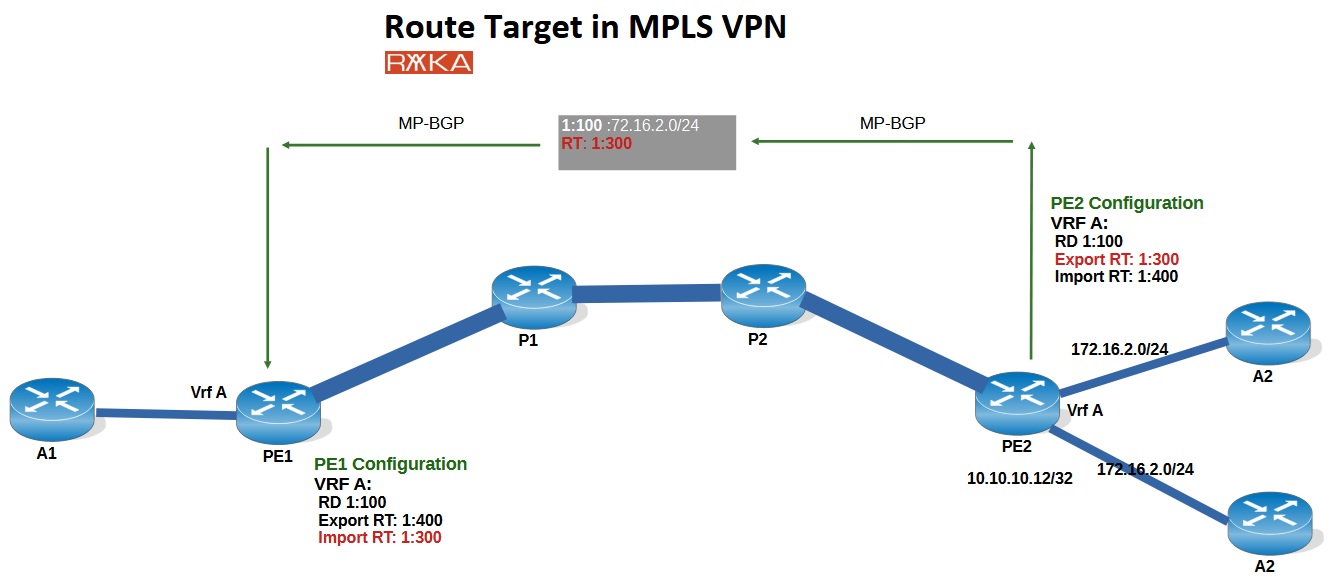
In the given topology, on PE2, VRF A is configured with Export RT 1:300 and Import RT 1:400. The Export RT (1:300) is the value attached to the route and advertised via MP-BGP.
When this route reaches PE1, it will be imported into VRF A only if the attached RT (1:300) matches the Import RT configured under VRF A on PE1. In this case, PE1 is indeed configured with Import RT 1:300, which allows it to accept and import the route from PE2.
This mechanism helps illustrate how RTs control route distribution between VRFs across PE routers in an MPLS VPN. Using RTs in this way enables the creation of flexible VPN topologies.
RT Design in various Topologies in MPLS VPN
Based on the explanation above, let’s now discuss how to design import and export Route Targets (RTs) for different MPLS VPN topologies.
Full-Mesh Topology in MPLS VPN
We’ll start with the full-mesh topology, where all customer sites need to communicate with each other directly.
For example, in the figure below, Customer A has three sites connected to the service provider’s edge routers: PE1, PE2, and PE3. To establish a full-mesh topology, we need to ensure that the routes exported by one site are imported by all other sites of the same customer.
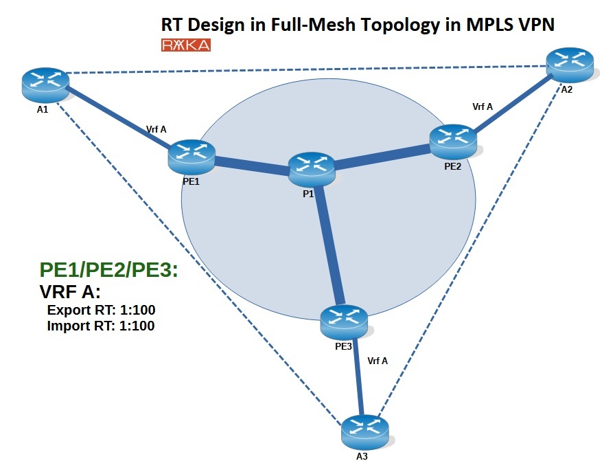
To achieve this, the simplest and most effective method is to configure the same RT value as both the export and import RT on all PE routers for that customer. This ensures that any route exported by one site is automatically imported by the others.
In this example, we configure RT 1:100 as both the export and import RT under the VRF for Customer A on all PE routers (PE1, PE2, and PE3). This setup provides full-mesh connectivity, allowing seamless communication between all sites of Customer A.
Hub-and-Spoke Topology in MPLS VPN
The next topology is the hub-and-spoke design, where customer sites are only allowed to communicate with a central (hub) site, and not with each other.
In this example, Customer A has three sites: A1 (the central office), and A2 and A3 (the spoke sites). A2 and A3 are only permitted to communicate with A1, and not with each other.
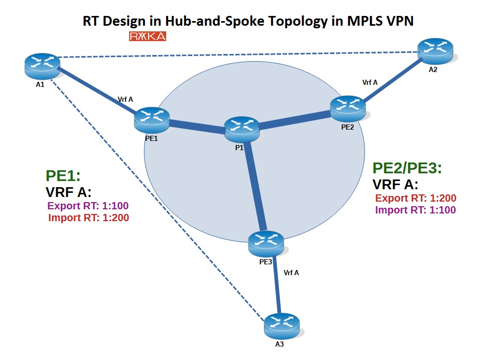
To implement this in MPLS VPN, we carefully assign export and import Route Targets (RTs) to control route distribution:
On PE1 (connected to the hub site A1), we configure:
Export RT:
1:100Import RT:
1:200
On PE2 and PE3 (connected to spoke sites A2 and A3), we configure:
Export RT:
1:200Import RT:
1:100
This RT design ensures:
Routes from A2 and A3 (spokes) are exported with
1:200, which the hub site A1 imports via1:200.Routes from the hub site A1 are exported with
1:100, which the spoke sites import via1:100.Since A2 and A3 do not import each other’s routes, they cannot communicate directly.
This achieves a clean and controlled hub-and-spoke communication model for Customer A.
It’s important to note that in a hub-and-spoke topology, customer sites cannot communicate with each other, even indirectly through the central site. This limitation is due to the behavior of iBGP, where routes learned via iBGP are not re-advertised to other iBGP peers.
In other words, when a route from site A2 is advertised to the central site A1 via the iBGP session between PE2 and PE1, that route is not re-advertised from PE1 to PE3 (which connects to A3) over the iBGP session. This is because iBGP, by design, does not propagate routes learned from one iBGP peer to another.
This default iBGP behavior reinforces the hub-and-spoke model by ensuring that spoke sites like A2 and A3 can only communicate with the hub (A1) and not with each other—exactly as intended in this topology.

Central Service Topology in MPLS VPN
The next topology is the central services topology, where multiple customers are provided access to a shared service, such as a voice gateway.
In this example, we have two customers, A and B, each with two sites and their own internal connectivity. In addition, there is a voice gateway connected to PE1, which acts as a central service. Any customer who subscribes to the service can access the voice gateway from their central site.
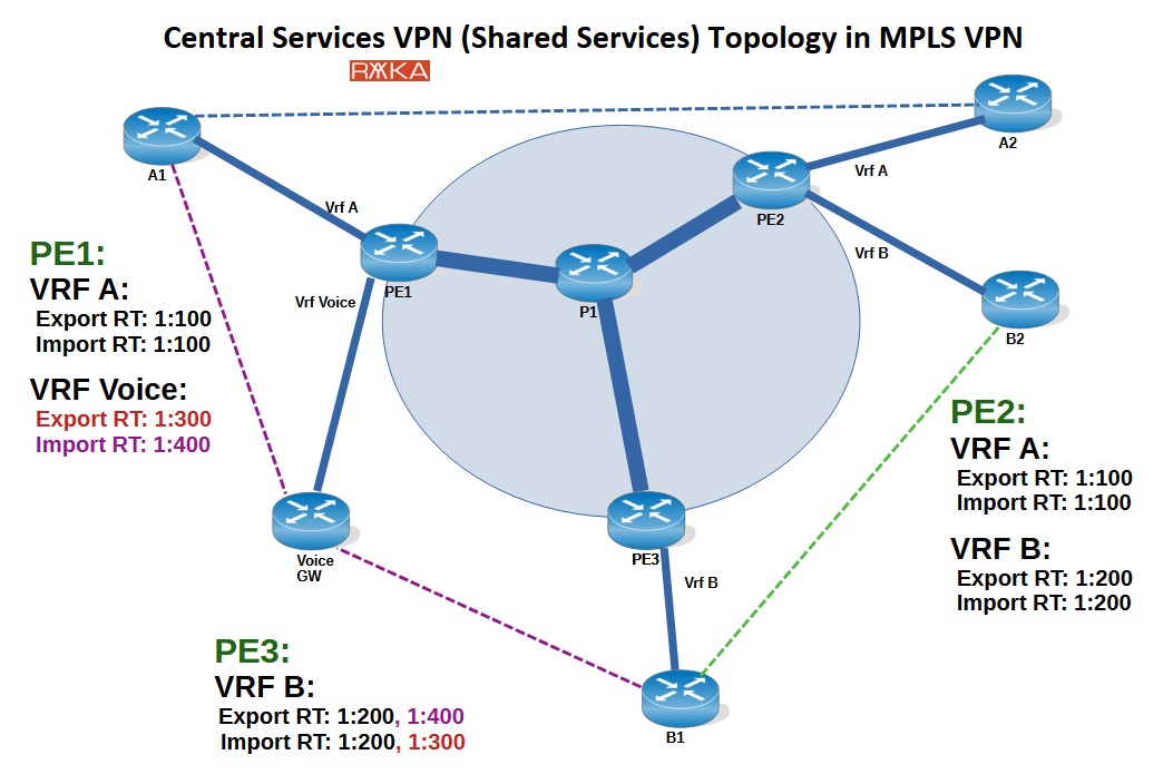
To support this model, we use Route Targets (RTs) to control route import/export behavior:
Customer A uses:
Export RT:
1:100Import RT:
1:100
Customer B uses:
Export RT:
1:200Import RT:
1:200
These ensure that each customer has full-mesh internal connectivity between their own sites.
For the voice gateway service, we configure:
Export RT:
1:300Import RT:
1:400
Now, for a customer to access the voice gateway:
The customer’s VRF must import the voice gateway’s exported RT (
1:300) to receive its routes.The voice gateway must import the RT exported by the customer’s central site (
1:100for A,1:200for B), by including that as an import RT in its configuration.
This two-way route exchange ensures that:
The customer receives routes to reach the voice gateway.
The voice gateway receives routes to reach the customer’s central site.
This example also illustrates that a single VRF can have multiple export and import RTs. In MPLS VPN, a route received via MP-BGP is imported into a VRF if its RT matches at least one of the import RTs configured for that VRF.
Extranet Topology in MPLS VPN
Finally Extranet VPN topology that allows controlled communication between different VPNs or customers—usually for business-to-business (B2B) integration.
Unlike a typical MPLS VPN where each customer is isolated in their own virtual private network, an Extranet VPN is used when two or more customers (or organizations) need to share certain services or resources, while still keeping the rest of their networks separate.
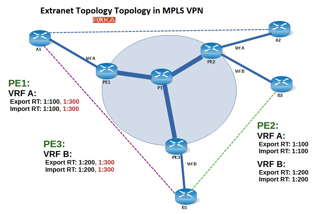
In this example, we have two customers, A and B, each with two sites and full internal connectivity between their own sites. However, there is also a requirement for connectivity between the central offices of customer A and customer B to allow shared access to certain services.
To support this topology, we configure the following Route Targets (RTs):
Customer A (internal connectivity):
Export RT:
1:100Import RT:
1:100
Customer B (internal connectivity):
Export RT:
1:200Import RT:
1:200
Shared service between central offices of A and B:
Export RT:
1:300Import RT:
1:300
(applied only to the VRFs of the central sites of A and B)
This configuration ensures:
Full isolation within each customer’s network.
Controlled route exchange only between the central offices of A and B.
Shared services are accessible only where explicitly allowed.