An OSPF sham link is a virtual link between PE routers over the MPLS backbone, used when a backdoor link exists between two OSPF sites in the same area. It ensures that the MPLS VPN path is seen as intra-area and preferred over the backdoor, which would otherwise appear more attractive to OSPF. This lesson covers the concept and simulates its behavior.
OSPF Sham Link Fundamental
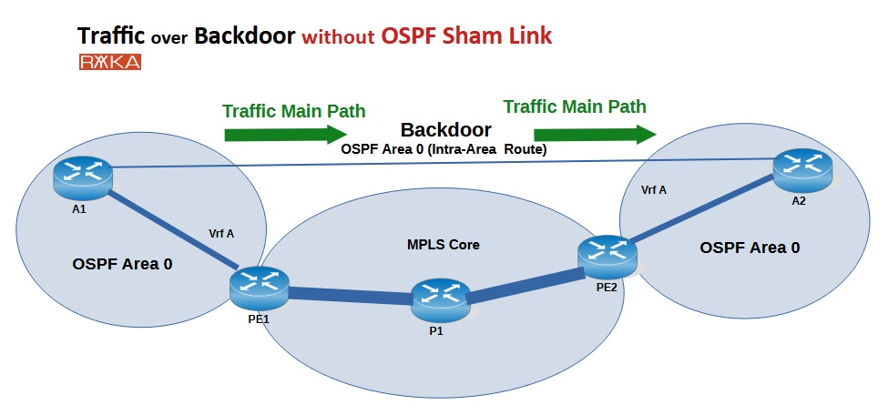
When two OSPF sites in the same area are connected both through an MPLS VPN backbone and a backdoor link, OSPF typically prefers the backdoor path. This is because routes over the backdoor are seen as intra-area, while those over the MPLS VPN are treated as inter-area or external.
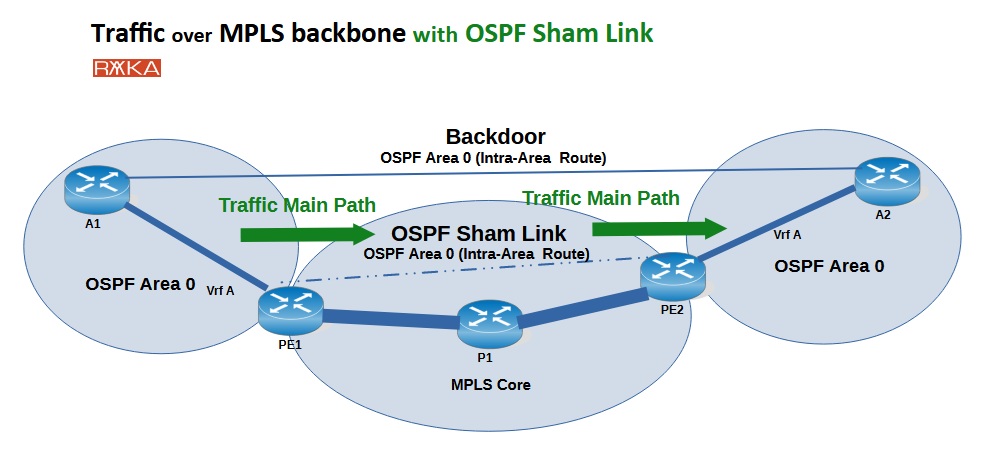
An OSPF sham link is a virtual, point-to-point intra-area link configured between PE routers across the MPLS core. It allows Type 1 and Type 2 LSAs to be exchanged directly between the PEs, maintaining intra-area route consistency. As a result, OSPF treats VPN routes as intra-area, ensuring the MPLS path is preferred over the backdoor when its cost is lower.
OSPF Sham Link Configuration Example
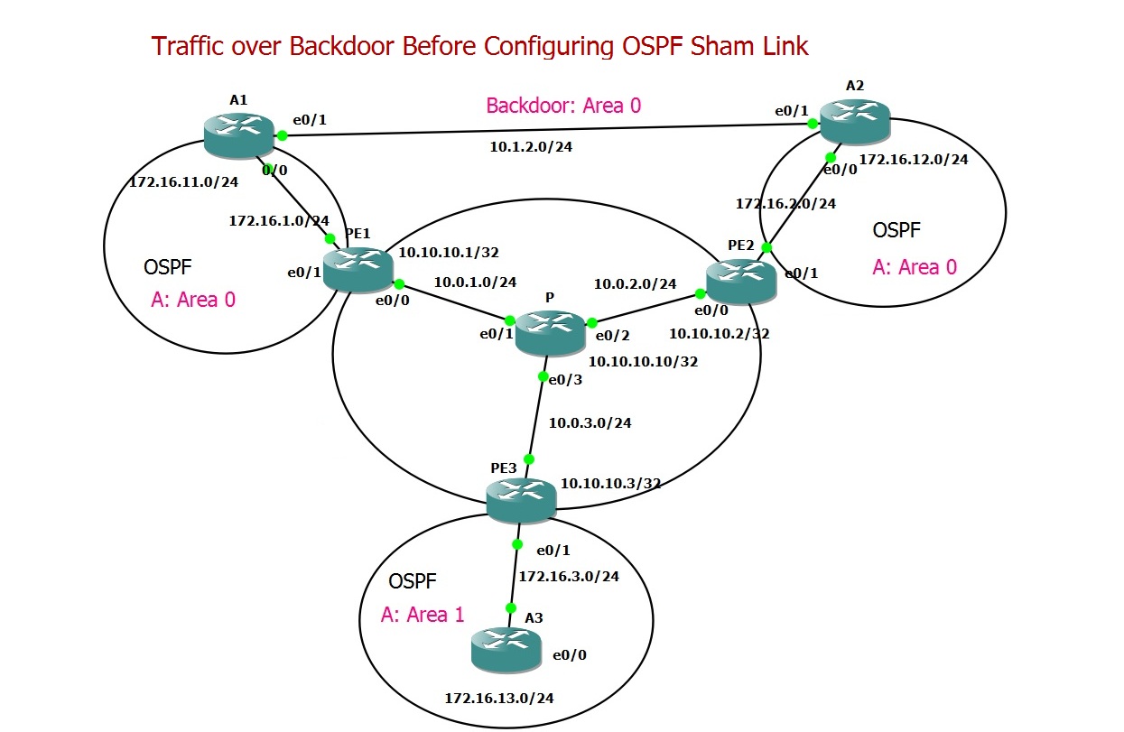
This configuration example involves Customer “A”, which has three sites connected to PE1, PE2, and PE3, all linked through an MPLS Layer 3 VPN backbone. Sites A1 and A2 belong to OSPF Area 0, while Site A3 is in Area 1.
In addition to MPLS connectivity, A1 and A2 also have a redundant backdoor link, intended to serve as a backup path if MPLS connectivity fails.
However, contrary to our intention, OSPF prefers the backdoor link by default. This happens because A1 and A2 receive each other’s routes via Type 3 LSAs (inter-area) over the MPLS backbone (the OSPF Superbackbone), but see each other via Type 1 or 2 LSAs (intra-area) over the backdoor.
Since OSPF always prefers intra-area routes over inter-area routes, the backdoor path becomes the primary one — even when MPLS is fully functional.
Traffic over Backdoor Before Configuring OSPF Sham Link
Let’s review the configuration and examine the LSA types exchanged between different sites before adding the OSPF sham link.
The MPLS and OSPF backbone is already configured, and VPNv4 BGP is established between PE1, PE2, and PE3. On each PE router, OSPF is configured toward the CE routers. To distinguish between the backbone OSPF process and the PE-CE OSPF process, the latter is configured under VRF A using OSPF process ID 100.
We redistribute OSPF routes from VRF A into BGP, and vice versa — BGP routes into OSPF within VRF A. This setup enables end-to-end routing between customer sites over the MPLS backbone.
Additionally, OSPF Area 0 is configured directly between Sites A1 and A2 over the backdoor link.
## A1
interface Loopback0
 ip address 172.16.11.1 255.255.255.0
!
interface Loopback100
 ip address 100.100.100.100 255.255.255.255
!
interface Ethernet0/0
 ip address 172.16.1.2 255.255.255.0
!
interface Ethernet0/1
 ip address 10.1.2.1 255.255.255.0
 ip ospf cost 50
!
router ospf 1
 redistribute connected subnets
 network 10.1.2.0 0.0.0.255 area 0
 network 172.16.0.0 0.0.255.255 area 0
## A2
interface Loopback0
 ip address 172.16.12.1 255.255.255.0
!
interface Ethernet0/0
 ip address 172.16.2.2 255.255.255.0
!
interface Ethernet0/1
 ip address 10.1.2.2 255.255.255.0
!
router ospf 1
 network 10.1.2.0 0.0.0.255 area 0
 network 172.16.0.0 0.0.255.255 area 0
## A3
interface Loopback0
 ip address 172.16.13.1 255.255.255.0
!
interface Ethernet0/0
 ip address 172.16.3.2 255.255.255.0
!
router ospf 1
 network 172.16.0.0 0.0.255.255 area 1
## PE1
hostname PE1
!
ip vrf A
 rd 1:100
 route-target export 1:100
 route-target import 1:100
!
ip cef
!
mpls label protocol ldp
!
interface Loopback0
 ip address 10.10.10.1 255.255.255.255
!
interface Ethernet0/0
 ip address 10.0.1.1 255.255.255.0
 mpls ip
!
interface Ethernet0/1
 ip vrf forwarding A
 ip address 172.16.1.1 255.255.255.0
!
router ospf 100 vrf A
 redistribute bgp 65001 subnets
 network 172.16.0.0 0.0.255.255 area 0
!
router ospf 1
 network 10.0.0.0 0.255.255.255 area 0
!
router bgp 65001
 bgp log-neighbor-changes
 neighbor 10.10.10.2 remote-as 65001
 neighbor 10.10.10.2 update-source Loopback0
 neighbor 10.10.10.3 remote-as 65001
 neighbor 10.10.10.3 update-source Loopback0
 !
 address-family vpnv4
  neighbor 10.10.10.2 activate
  neighbor 10.10.10.2 send-community both
  neighbor 10.10.10.2 next-hop-self
  neighbor 10.10.10.3 activate
  neighbor 10.10.10.3 send-community both
  neighbor 10.10.10.3 next-hop-self
 exit-address-family
 !
 address-family ipv4 vrf A
  redistribute ospf 100 match internal external 1 external 2
 exit-address-family
!
mpls ldp router-id Loopback0
## PE2
hostname PE2
!
ip vrf A
 rd 1:100
 route-target export 1:100
 route-target import 1:100
!
ip cef
!
mpls label protocol ldp
!
interface Loopback0
 ip address 10.10.10.2 255.255.255.255
!
interface Ethernet0/0
 ip address 10.0.2.2 255.255.255.0
 mpls ip
!
interface Ethernet0/1
 ip vrf forwarding A
 ip address 172.16.2.1 255.255.255.0
!
router ospf 100 vrf A
 redistribute bgp 65001 subnets
 network 172.16.0.0 0.0.255.255 area 0
!
router ospf 1
 network 10.0.0.0 0.255.255.255 area 0
!
router bgp 65001
 bgp log-neighbor-changes
 neighbor 10.10.10.1 remote-as 65001
 neighbor 10.10.10.1 update-source Loopback0
 neighbor 10.10.10.3 remote-as 65001
 neighbor 10.10.10.3 update-source Loopback0
 !
 address-family vpnv4
  neighbor 10.10.10.1 activate
  neighbor 10.10.10.1 send-community both
  neighbor 10.10.10.1 next-hop-self
  neighbor 10.10.10.3 activate
  neighbor 10.10.10.3 send-community both
  neighbor 10.10.10.3 next-hop-self
 exit-address-family
 !
 address-family ipv4 vrf A
  redistribute ospf 100
 exit-address-family
!
mpls ldp router-id Loopback0
## PE3
hostname PE3
!
ip vrf A
 rd 1:100
 route-target export 1:100
 route-target import 1:100
!
ip cef
!
mpls label protocol ldp
!
interface Loopback0
 ip address 10.10.10.3 255.255.255.255
!
interface Ethernet0/0
 ip address 10.0.3.3 255.255.255.0
 mpls ip
!
interface Ethernet0/1
 ip vrf forwarding A
 ip address 172.16.3.1 255.255.255.0
!
router ospf 100 vrf A
 redistribute bgp 65001 subnets
 network 172.16.0.0 0.0.255.255 area 1
!
router ospf 1
 network 10.0.0.0 0.255.255.255 area 0
!
router bgp 65001
 bgp log-neighbor-changes
 neighbor 10.10.10.1 remote-as 65001
 neighbor 10.10.10.1 update-source Loopback0
 neighbor 10.10.10.2 remote-as 65001
 neighbor 10.10.10.2 update-source Loopback0
 !
 address-family vpnv4
  neighbor 10.10.10.1 activate
  neighbor 10.10.10.1 send-community both
  neighbor 10.10.10.1 next-hop-self
  neighbor 10.10.10.2 activate
  neighbor 10.10.10.2 send-community both
  neighbor 10.10.10.2 next-hop-self
 exit-address-family
 !
 address-family ipv4 vrf A
  redistribute ospf 100
 exit-address-family
!
mpls ldp router-id Loopback0
## P
hostname P
!
ip cef
!
mpls label protocol ldp
!
interface Loopback0
 ip address 10.10.10.10 255.255.255.255
!
interface Ethernet0/1
 ip address 10.0.1.10 255.255.255.0
 mpls ip
!
interface Ethernet0/2
 ip address 10.0.2.10 255.255.255.0
 mpls ip
!
interface Ethernet0/3
 ip address 10.0.3.10 255.255.255.0
 mpls ip
!
router ospf 1
 network 10.0.0.0 0.255.255.255 area 0
!
mpls ldp router-id Loopback0
When we check the OSPF routing table on Site A1, we observe the following:
The PE-to-PE path (via MPLS backbone) is seen as inter-area or external, e.g., for routes between A1 and A3.
The direct backdoor link between A1 and A2 is seen as an intra-area route.
As a result, OSPF prefers the backdoor path between Sites A1 and A2, even when MPLS is available.
A1#show ip route ospf
...
Gateway of last resort is not set

      172.16.0.0/16 is variably subnetted, 8 subnets, 2 masks
O        172.16.2.0/24 [110/20] via 10.1.2.2, 00:02:12, Ethernet0/1
O IA     172.16.3.0/24 [110/11] via 172.16.1.1, 00:14:41, Ethernet0/0
O        172.16.12.1/32 [110/11] via 10.1.2.2, 00:02:12, Ethernet0/1
O IA     172.16.13.1/32 [110/21] via 172.16.1.1, 00:14:31, Ethernet0/0
A1#traceroute 172.16.12.1 source 172.16.11.1
Type escape sequence to abort.
Tracing the route to 172.16.12.1
VRF info: (vrf in name/id, vrf out name/id)
  1 10.1.2.2 6 msec 5 msec 6 msec
A1#
Configure OSPF Sham Link
To configure the OSPF sham link, I created Loopback50 interfaces on both PE1 and PE2 within VRF A, assigning them IP addresses 1.1.1.1 and 2.2.2.2 respectively. These loopbacks were redistributed into BGP under the VRF to ensure reachability across the MPLS backbone. Then, under the OSPF process 100 in VRF A, I configured a sham link in Area 0 between the two loopback addresses. This creates a virtual intra-area connection between PE1 and PE2, allowing OSPF to treat MPLS routes as intra-area and prefer them over the backdoor path.
## PE1
interface Loopback50
 ip vrf forwarding A
 ip address 1.1.1.1 255.255.255.255
!
router bgp 65001
 address-family ipv4 vrf A
  redistribute connected
!
router ospf 100 vrf A
 area 0 sham-link 1.1.1.1 2.2.2.2
## PE2
interface Loopback50
 ip vrf forwarding A
 ip address 2.2.2.2 255.255.255.255
!
router bgp 65001
 address-family ipv4 vrf A
  redistribute connected
!
router ospf 100 vrf A
 area 0 sham-link 2.2.2.2 1.1.1.1
Verifying OSPF Sham Link
After configuring the sham link between PE1 and PE2 using their loopback interfaces, the following output confirms successful verification:
✅ Ping Success:
ping vrf A 2.2.2.2 source 1.1.1.1from PE1 succeeds with 100% success rate, verifying IP reachability between sham link endpoints across the MPLS core.✅ OSPF Adjacency Up: Syslog messages show that OSPF process 100 formed a FULL adjacency over the sham link interface (OSPF_SL0), confirming successful OSPF neighbor establishment.
✅ Neighbor Table:
show ip ospf 100 neighborshows a FULL state with neighbor 172.16.2.1 over the OSPF_SL0 interface.✅ Sham Link Status:
show ip ospf sham-linksconfirms the sham link is up, area is 0, state is POINT_TO_POINT, and the link runs as a demand circuit with a cost of 1.✅ Interface Verification:
show ip ospf interfaceindicates OSPF_SL0 is up, type is SHAM_LINK, cost 1, and the link has 1 fully adjacent neighbor.✅ Routing Table Check: On CE router A1, routes to loopbacks of PE1 (1.1.1.1) and PE2 (2.2.2.2) appear as OSPF external (E2) routes via PE, confirming MPLS-based OSPF reachability is established.
PE1#ping vrf A 2.2.2.2 source 1.1.1.1
Type escape sequence to abort.
Sending 5, 100-byte ICMP Echos to 2.2.2.2, timeout is 2 seconds:
Packet sent with a source address of 1.1.1.1
!!!!!
Success rate is 100 percent (5/5), round-trip min/avg/max = 3/4/5 ms
PE1#
PE1(config-router)#
*Aug  4 11:34:07.796: %OSPF-5-ADJCHG: Process 100, Nbr 172.16.2.1 on OSPF_SL0 from LOADING to FULL, Loading Done
!
PE2(config-router)#
*Aug  4 11:34:07.796: %OSPF-5-ADJCHG: Process 100, Nbr 172.16.1.1 on OSPF_SL0 from LOADING to FULL, Loading Done
PE1#show ip ospf 100 neighbor

Neighbor ID     Pri   State           Dead Time   Address         Interface
172.16.2.1        0   FULL/  -           -        2.2.2.2         OSPF_SL0
172.16.11.1       1   FULL/DR         00:00:38    172.16.1.2      Ethernet0/1
PE1#show ip ospf sham-links
Sham Link OSPF_SL0 to address 2.2.2.2 is up
Area 0 source address 1.1.1.1
  Run as demand circuit
  DoNotAge LSA allowed. Cost of using 1 State POINT_TO_POINT,
  Timer intervals configured, Hello 10, Dead 40, Wait 40,
    Hello due in 00:00:08
    Adjacency State FULL (Hello suppressed)
    Index 2/2, retransmission queue length 0, number of retransmission 0
    First 0x0(0)/0x0(0) Next 0x0(0)/0x0(0)
    Last retransmission scan length is 0, maximum is 0
    Last retransmission scan time is 0 msec, maximum is 0 msec
PE1#show ip ospf interface
...
OSPF_SL0 is up, line protocol is up
  Internet Address 0.0.0.0/0, Area 0, Attached via Not Attached
  Process ID 100, Router ID 172.16.1.1, Network Type SHAM_LINK, Cost: 1
  Topology-MTID    Cost    Disabled    Shutdown      Topology Name
        0           1         no          no            Base
  Configured as demand circuit
  Run as demand circuit
  DoNotAge LSA allowed
  Transmit Delay is 1 sec, State POINT_TO_POINT
  Timer intervals configured, Hello 10, Dead 40, Wait 40, Retransmit 5
    oob-resync timeout 40
    Hello due in 00:00:02
  Supports Link-local Signaling (LLS)
  Cisco NSF helper support enabled
  IETF NSF helper support enabled
  Index 2/2, flood queue length 0
  Next 0x0(0)/0x0(0)
  Last flood scan length is 1, maximum is 1
  Last flood scan time is 0 msec, maximum is 0 msec
  Neighbor Count is 1, Adjacent neighbor count is 1
    Adjacent with neighbor 172.16.2.1  (Hello suppressed)
  Suppress hello for 1 neighbor(s)
...
Traffic over MPLS after Configuring OSPF Sham Link
Now, Sites A1 and A2 see each other through two intra-area paths: one over the MPLS VPN (via the OSPF sham link) and one over the backdoor link. To ensure that traffic is forwarded over the MPLS path, I increased the OSPF cost on the backdoor interface (Ethernet0/1) at Site A1 to 50. This adjustment makes the MPLS path more attractive to OSPF, ensuring it is selected as the preferred route over the higher-cost backdoor link.
## A1
interface Ethernet0/1
 ip ospf cost 50
A1#show ip route ospf
...
Gateway of last resort is not set

      1.0.0.0/32 is subnetted, 1 subnets
O E2     1.1.1.1 [110/1] via 172.16.1.1, 00:01:37, Ethernet0/0
      2.0.0.0/32 is subnetted, 1 subnets
O E2     2.2.2.2 [110/1] via 172.16.1.1, 00:06:09, Ethernet0/0
      172.16.0.0/16 is variably subnetted, 8 subnets, 2 masks
O        172.16.2.0/24 [110/21] via 172.16.1.1, 00:00:05, Ethernet0/0
O IA     172.16.3.0/24 [110/11] via 172.16.1.1, 00:38:25, Ethernet0/0
O        172.16.12.1/32 [110/22] via 172.16.1.1, 00:00:05, Ethernet0/0
O IA     172.16.13.1/32 [110/21] via 172.16.1.1, 00:38:15, Ethernet0/0
A1#traceroute 172.16.12.1 source 172.16.11.1
Type escape sequence to abort.
Tracing the route to 172.16.12.1
VRF info: (vrf in name/id, vrf out name/id)
  1 172.16.1.1 6 msec 1 msec 4 msec
  2 10.0.1.10 [MPLS: Labels 19/16 Exp 0] 5 msec 5 msec 5 msec
  3 172.16.2.1 [MPLS: Label 16 Exp 0] 5 msec 1 msec 4 msec
  4 172.16.2.2 2 msec 4 msec 5 msec
A1#
After increasing the OSPF cost on the backdoor interface at Site A1 to 50, the routing table shows that OSPF now prefers routes via the MPLS VPN path (next hop 172.16.1.1) instead of the backdoor. The traceroute output confirms that traffic from A1 to a remote subnet passes through the MPLS network, traversing PE routers identified by MPLS labels. This confirms that adjusting the backdoor cost successfully forces OSPF to route traffic over the MPLS VPN instead of the backdoor link.