MPLS VPN hub-and-spoke topology is the focus of this lesson. In this design, customer branch sites communicate exclusively with the central office, not with each other. We will configure this topology using route targets (RTs), as introduced in the previous lesson.
MPLS VPN Hub and Spoke Topology
In the previous lesson, we discussed how to design route-targets to create a hub-and-spoke topology for a customer using MPLS VPN technology.
RT Design in Hub and Spoke Topology
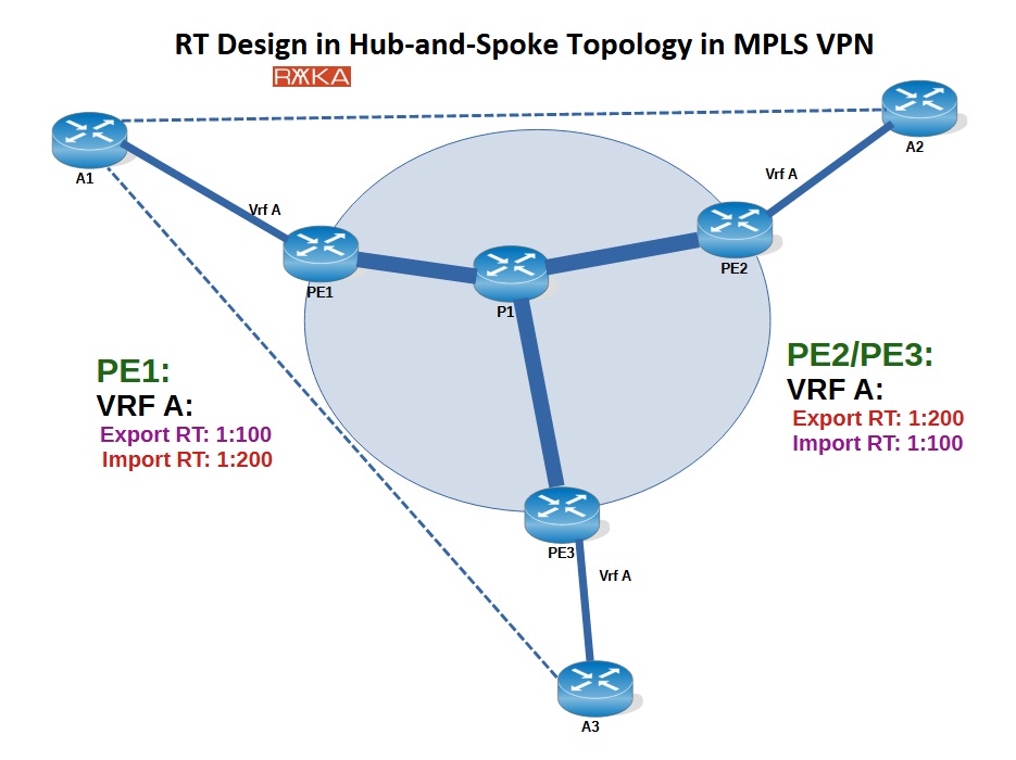
In a hub-and-spoke MPLS VPN design, spoke sites (A2 and A3) communicate only with a central hub site (A1) and not with each other. This is accomplished by carefully configuring Route Target (RT) import and export policies on the Provider Edge (PE) routers. The key is to configure the PE router connected to the hub site with export and import RTs that are the reverse of those configured on the PE routers connected to the spoke sites.
For example, on PE1 (connected to the central site A1), the export RT is set to 1:100 and the import RT to 1:200. On the spoke-site routers PE2 and PE3 (connected to A2 and A3), the configuration is reversed: export RT is 1:200 and import RT is 1:100.
This RT setup ensures the router advertised by spoke sites are received by hub and the routes advertised by hub site is received by spoke sites.
Spoke sites can not reaceive each other route even through hub sites because in iBGP’s rule of not re-advertising routes learned from one iBGP peer to another enforces this behavior, preventing spoke-to-spoke communication through the hub.
MPLS VON Hub and Spoke Topology Configuration Example
I have now prepared the same topology so that we can examine the final configuration and results. This topology includes an MPLS service provider network with three PE routers and one P router. A customer labeled “A” has one central office (A1) and two branches (A2 and A3), which are connected to the MPLS network via PE1 (central office), PE2, and PE3 (branches).
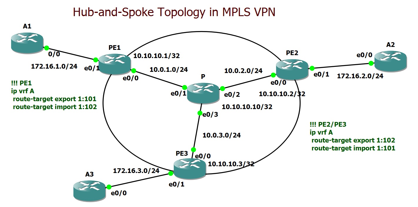
Just as we discussed and demonstrated in previous lessons, I started by building the topology by configuring IP addressing, OSPF, and LDP to enable MPLS functionality.
hostname P
!
ip cef
!
mpls label protocol ldp
!
interface Loopback0
 ip address 10.10.10.10 255.255.255.255
!
interface Ethernet0/1
 ip address 10.0.1.10 255.255.255.0
 mpls ip
!
interface Ethernet0/2
 ip address 10.0.2.10 255.255.255.0
 mpls ip
!
interface Ethernet0/3
 ip address 10.0.3.10 255.255.255.0
 mpls ip
!
router ospf 1
 network 10.0.0.0 0.255.255.255 area 0
!
mpls ldp router-id Loopback0
hostname PE1
!
ip cef
!
mpls label protocol ldp
!
interface Loopback0
 ip address 10.10.10.1 255.255.255.255
!
interface Ethernet0/0
 ip address 10.0.1.1 255.255.255.0
 mpls ip
!
interface Ethernet0/1
 ip vrf forwarding A
 ip address 172.16.1.1 255.255.255.0
!
router ospf 1
 network 10.0.0.0 0.255.255.255 area 0
!
mpls ldp router-id Loopback0
On each PE router, I configured VRF “A” with appropriate route-target values for import and export, consistent with our earlier discussions and the provided topology. The interfaces connected to the customer sites are then assigned to VRF A.
hostname PE1
!
ip vrf A
 rd 1:100
 route-target export 1:101
 route-target import 1:102
!
interface Ethernet0/1
 ip vrf forwarding A
 ip address 172.16.1.1 255.255.255.0
hostname PE2
!
ip vrf A
 rd 1:100
 route-target export 1:102
 route-target import 1:101
!
interface Ethernet0/1
 ip vrf forwarding A
 ip address 172.16.2.1 255.255.255.0
hostname PE3
!
ip vrf A
 rd 1:100
 route-target export 1:102
 route-target import 1:101
!
interface Ethernet0/1
 ip vrf forwarding A
 ip address 172.16.3.1 255.255.255.0
Next, on each PE router, I established BGP peering with the other two PE routers using the VPNv4 address family. Within the IPv4 address family under VRF A, I redistributed the customer-connected routes into BGP to allow for route exchange between the PE routers.
hostname PE1
!
router bgp 65001
 bgp log-neighbor-changes
 neighbor 10.10.10.2 remote-as 65001
 neighbor 10.10.10.2 update-source Loopback0
 neighbor 10.10.10.3 remote-as 65001
 neighbor 10.10.10.3 update-source Loopback0
 !
 address-family vpnv4
  neighbor 10.10.10.2 activate
  neighbor 10.10.10.2 send-community both
  neighbor 10.10.10.2 next-hop-self
  neighbor 10.10.10.3 activate
  neighbor 10.10.10.3 send-community both
  neighbor 10.10.10.3 next-hop-self
 exit-address-family
 !
 address-family ipv4 vrf A
  redistribute connected
 exit-address-family
hostname PE2
!
router bgp 65001
 bgp log-neighbor-changes
 neighbor 10.10.10.1 remote-as 65001
 neighbor 10.10.10.1 update-source Loopback0
 neighbor 10.10.10.3 remote-as 65001
 neighbor 10.10.10.3 update-source Loopback0
 !
 address-family vpnv4
  neighbor 10.10.10.1 activate
  neighbor 10.10.10.1 send-community both
  neighbor 10.10.10.1 next-hop-self
  neighbor 10.10.10.3 activate
  neighbor 10.10.10.3 send-community both
  neighbor 10.10.10.3 next-hop-self
 exit-address-family
 !
 address-family ipv4 vrf A
  redistribute connected
 exit-address-family
On the customer edge routers, only a default route is configured, pointing toward the connected PE router. This ensures that all traffic is routed through the MPLS network.
hostname A1
!
interface eth0/0
 no shutdown
 ip address 172.16.1.2 255.255.255.0
!
ip route 0.0.0.0 0.0.0.0 172.16.1.1
Verify Hub and Spoke Connectivity
To verify that the hub-and-spoke connectivity is functioning correctly, we test connectivity from the central office to the branches, as well as between the branches themselves.
A1#traceroute 172.16.2.2
Type escape sequence to abort.
Tracing the route to 172.16.2.2
VRF info: (vrf in name/id, vrf out name/id)
  1 172.16.1.1 5 msec 5 msec 5 msec
  2 10.0.1.10 [MPLS: Labels 20/22 Exp 0] 6 msec 6 msec 4 msec
  3 172.16.2.1 5 msec 5 msec 5 msec
  4 172.16.2.2 5 msec 5 msec 1 msec
A1#traceroute 172.16.3.2
Type escape sequence to abort.
Tracing the route to 172.16.3.2
VRF info: (vrf in name/id, vrf out name/id)
  1 172.16.1.1 6 msec 6 msec 5 msec
  2 10.0.1.10 [MPLS: Labels 21/22 Exp 0] 5 msec 4 msec 4 msec
  3 172.16.3.1 5 msec 5 msec 5 msec
  4 172.16.3.2 6 msec 0 msec 5 msec
A2#traceroute 172.16.3.2 source 172.16.2.2
Type escape sequence to abort.
Tracing the route to 172.16.3.2
VRF info: (vrf in name/id, vrf out name/id)
  1 172.16.2.1 6 msec 5 msec 4 msec
  2 172.16.2.1 !H  !H  !H
We observe that communication between the central office and each branch works as expected. However, the connectivity between the branches is not functioning as intended.
You can also verify the connectivity by checking the VPNv4 BGP table on PE1 and the other PE routers.
PE1#show bgp vpnv4 unicast all
BGP table version is 6, local router ID is 10.10.10.1
Status codes: s suppressed, d damped, h history, * valid, > best, i - internal,
              r RIB-failure, S Stale, m multipath, b backup-path, f RT-Filter,
              x best-external, a additional-path, c RIB-compressed,
Origin codes: i - IGP, e - EGP, ? - incomplete
RPKI validation codes: V valid, I invalid, N Not found

     Network          Next Hop            Metric LocPrf Weight Path
Route Distinguisher: 1:100 (default for vrf A)
 *>  172.16.1.0/24    0.0.0.0                  0         32768 ?
 *>i 172.16.2.0/24    10.10.10.2               0    100      0 ?
 *>i 172.16.3.0/24    10.10.10.3               0    100      0 ?
PE2#show bgp vpnv4 unicast all
BGP table version is 4, local router ID is 10.10.10.2
Status codes: s suppressed, d damped, h history, * valid, > best, i - internal,
              r RIB-failure, S Stale, m multipath, b backup-path, f RT-Filter,
              x best-external, a additional-path, c RIB-compressed,
Origin codes: i - IGP, e - EGP, ? - incomplete
RPKI validation codes: V valid, I invalid, N Not found

     Network          Next Hop            Metric LocPrf Weight Path
Route Distinguisher: 1:100 (default for vrf A)
 *>i 172.16.1.0/24    10.10.10.1               0    100      0 ?
 *>  172.16.2.0/24    0.0.0.0                  0         32768 ?
On PE1, which is connected to the central office, you will see routes for all branches, each pointing to its corresponding PE router. On the other PE routers, however, you will only see the route for the branch connected to that specific PE router, along with the route to reach the central office.