MPLS VPN control plane and data plane understanding is essential to grasp how MPLS VPNs operate. The control plane, powered by LDP and MP-BGP , are responsible for building and exchanging routing and label information that determines how traffic should flow across the network. In contrast, the data plane handles the actual forwarding of packets within the MPLS network, using the labels and paths established by the control plane.
MPLS VPN Control / Data Plane Fundamental
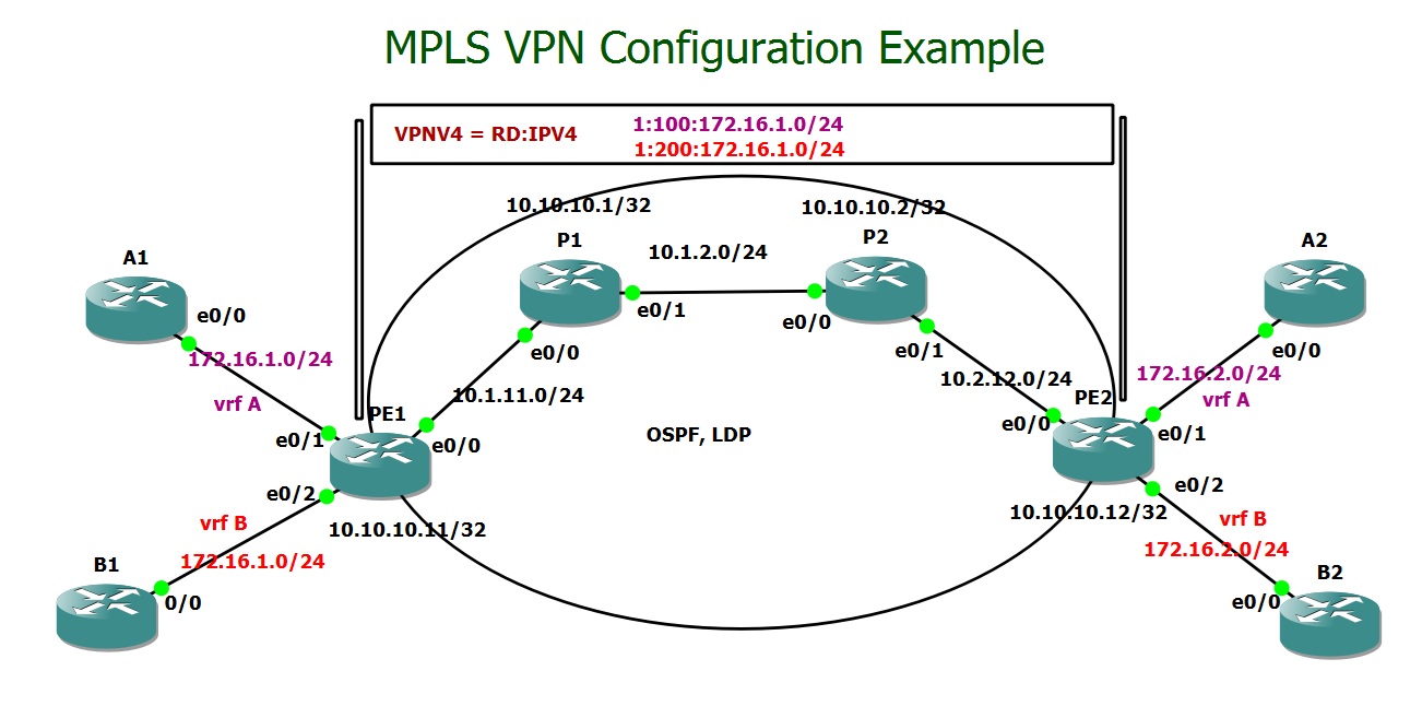
This is the MPLS VPN topology that we configured step by step in the previous lesson. In this section, we will shift our focus to the theoretical aspect of MPLS VPN operation. The service provider’s infrastructure consists of two Provider Edge (PE) routers connected through two intermediate Provider (P) routers. We have two customers—Customer A and Customer B—each with two sites: A1 and A2 for Customer A, and B1 and B2 for Customer B.
For this specific case, the control plane direction is from A2 to A1, as it is responsible for setting up the necessary routing and label information to enable data plane traffic to flow from A1 to A2. Therefore, we are examining a segment of the complete topology that involves only the devices and paths required for A1-to-A2 communication, including detailed insights into both control and data planes.
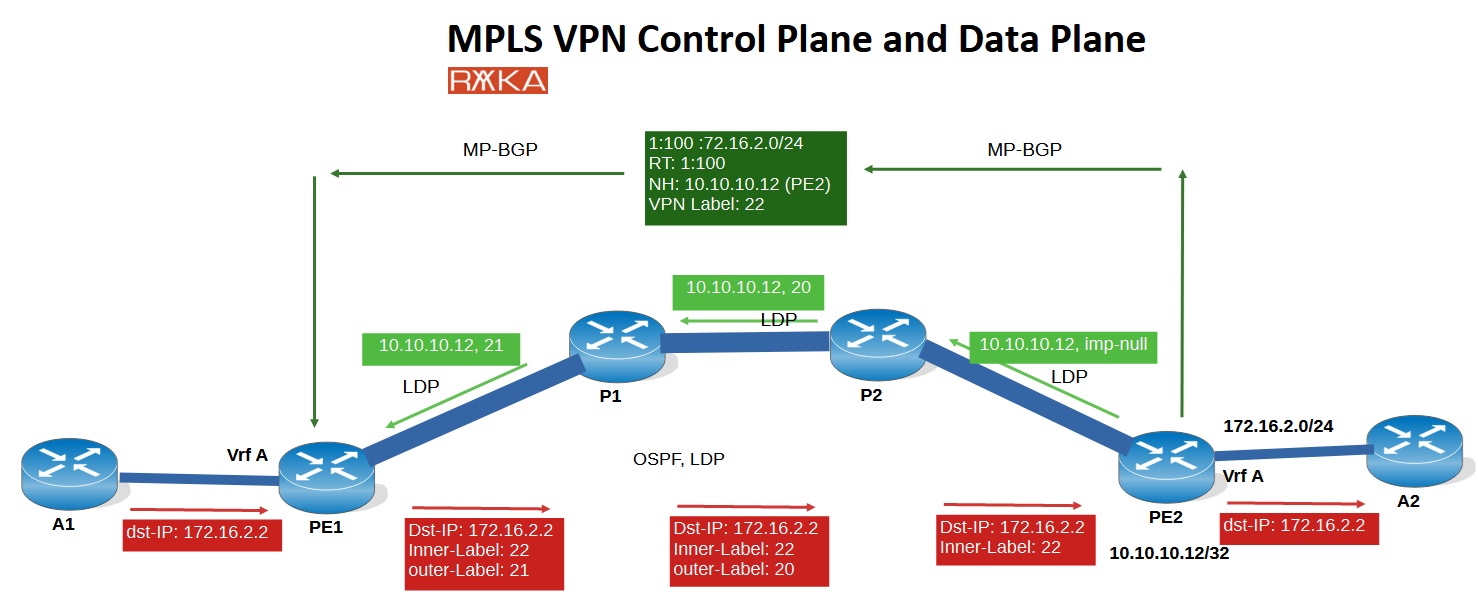
The control plane is divided into two components: LDP and MP-BGP. LDP operates from PE2 → P2 → P1 → PE1, represented in light green, while MP-BGP establishes a direct peering from PE2 to PE1, shown in dark green.
In contrast, the data plane carries actual traffic in the opposite direction—from A1 to A2—and is represented in red.
MPLS VPN Data Plane
First, let’s examine how actual traffic forwarding works in the data plane. After that, we’ll discuss how routing and label information is advertised via the control plane.
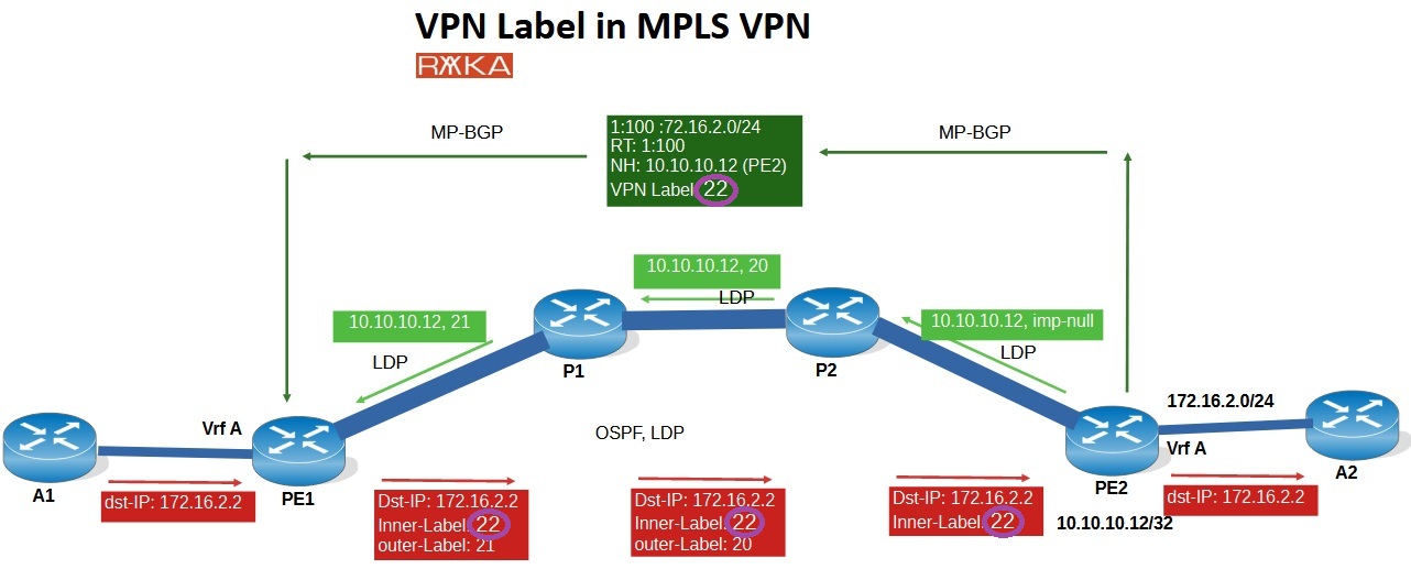
Client A1 sends traffic destined for IP address 172.16.2.2, which belongs to site A2. The default gateway for A1 is configured as PE1. When PE1 receives the packet on an interface associated with VRF A, it processes it as standard IP traffic. PE1 consults the CEF (FIB) table for VRF A, which determines that the packet should be forwarded with two labels: “21 22”.
PE1#show ip cef vrf A 172.16.2.2
172.16.2.0/24
  nexthop 10.1.11.1 Ethernet0/0 label 21 22
Label 21 is the outer label, assigned by LDP, which identifies the next hop toward PE2. This label is used to forward the packet across the MPLS core.
Label 22 is the inner label, also called the VPN label, which identifies the specific VPN or VRF the packet belongs to.
As the packet traverses the MPLS core, it is forwarded based on the LFIB, since the incoming packet is already label-switched.
On P1, the outer label (21) is swapped with a new label (20).
On P2, the outer label is popped due to Penultimate Hop Popping (PHP), meaning the packet arrives at PE2 with only the inner label (22).
P1#show mpls forwarding-table labels 21
Local      Outgoing   Prefix           Bytes Label   Outgoing   Next Hop
Label      Label      or Tunnel Id     Switched      interface
21         20         10.10.10.12/32   249839        Et0/1      10.1.2.2
P2#show mpls forwarding-table l
P2#show mpls forwarding-table labels 20
Local      Outgoing   Prefix           Bytes Label   Outgoing   Next Hop
Label      Label      or Tunnel Id     Switched      interface
20         Pop Label  10.10.10.12/32   232888        Et0/1      10.2.12.12
At PE2, the router receives the packet with the VPN label only. This inner label allows PE2 to determine which customer VRF the traffic belongs to—in this case, VRF A—and to forward the packet to the destination 172.16.2.2 in site A2.
PE2#show mpls forwarding-table labels 22
Local      Outgoing   Prefix           Bytes Label   Outgoing   Next Hop
Label      Label      or Tunnel Id     Switched      interface
22         No Label   172.16.2.0/24[V] 2898          aggregate/A
The VPN label (22) was originally distributed by PE2 through MP-BGP, which is part of the control plane. We will discuss how this label and routing information are exchanged in the control plane in a few minutes.
You can also verify data plane operation using the traceroute command. A traceroute between PE1 and PE2 allows you to observe how the LDP labels change at each hop within the MPLS core. Similarly, a traceroute from A1 to A2 reveals how the entire label stack (including both the LDP and VPN labels) evolves as the packet travels through the MPLS network.
PE1#traceroute 10.10.10.12 source 10.10.10.11
Type escape sequence to abort.
Tracing the route to 10.10.10.12
VRF info: (vrf in name/id, vrf out name/id)
  1 10.1.11.1 [MPLS: Label 21 Exp 0] 7 msec 6 msec 6 msec
  2 10.1.2.2 [MPLS: Label 20 Exp 0] 7 msec 4 msec 4 msec
  3 10.2.12.12 7 msec 5 msec 5 msec
A1#traceroute 172.16.2.2
Type escape sequence to abort.
Tracing the route to 172.16.2.2
VRF info: (vrf in name/id, vrf out name/id)
  1 172.16.1.1 5 msec 4 msec 5 msec
  2 10.1.11.1 [MPLS: Labels 21/22 Exp 0] 5 msec 5 msec 5 msec
  3 10.1.2.2 [MPLS: Labels 20/22 Exp 0] 5 msec 5 msec 5 msec
  4 172.16.2.1 4 msec 1 msec 5 msec
  5 172.16.2.2 0 msec 0 msec 1 msec
A1#
MPLS VPN Control Plane
For the control plane, we use two protocols: LDP and MP-BGP.
With LDP, customer traffic is forwarded through an MPLS tunnel (LSP) between PE routers, without requiring MPLS core routers to have knowledge of customer network prefixes. The core simply forwards packets based on labels.
With MP-BGP, customer routes are advertised between PE routers. Each customer route is only imported into the VRF of the PE router that is connected to that specific customer.
In the example shown, where traffic flows from A1 to A2, the label signaling using both LDP and MP-BGP is illustrated for the direction from PE2 to PE1.
LDP in Control Plane
Here’s how the LDP signaling works in this scenario:
PE2 sends a label “implicit-null” (imp-null) to P2 for the address 10.10.10.12 (PE2’s loopback), as PE2 is directly connected to that address.
P2 then generates and advertises label 20 for the same prefix (10.10.10.12) to P1.
P1, in turn, generates and sends label 21 for that prefix to PE1.
P2#show mpls ldp binding 10.10.10.12 32
  lib entry: 10.10.10.12/32, rev 15
        local binding:  label: 20
        remote binding: lsr: 10.10.10.12:0, label: imp-null
        remote binding: lsr: 10.10.10.1:0, label: 21
P1#show mpls ldp bindings 10.10.10.12 32
  lib entry: 10.10.10.12/32, rev 16
        local binding:  label: 21
        remote binding: lsr: 10.10.10.2:0, label: 20
        remote binding: lsr: 10.10.10.11:0, label: 21
P2#show mpls ldp binding 10.10.10.12 32
  lib entry: 10.10.10.12/32, rev 15
        local binding:  label: 20
        remote binding: lsr: 10.10.10.12:0, label: imp-null
        remote binding: lsr: 10.10.10.1:0, label: 21
This results in the label path for the LSP from PE1 to PE2: “21 → 20 → pop (implicit-null)”.
This means that PE1 will push label 21, which gets swapped to 20 at P1, and finally popped at P2 before reaching PE2.
PE1#show ip cef 10.10.10.12
10.10.10.12/32
  nexthop 10.1.11.1 Ethernet0/0 label 21
P1#show ip cef 10.10.10.12
10.10.10.12/32
  nexthop 10.1.2.2 Ethernet0/1 label 20
P2#show ip cef 10.10.10.12
10.10.10.12/32
  nexthop 10.2.12.12 Ethernet0/1
PE2#show ip cef 10.10.10.12
10.10.10.12/32
  receive for Loopback0
MP-BGP in Control Plane
In the figure, you can also see how the customer route 172.16.2.0/24 is advertised from PE2 to PE1 using the MP-BGP protocol.
Route Distinguisher (RD)
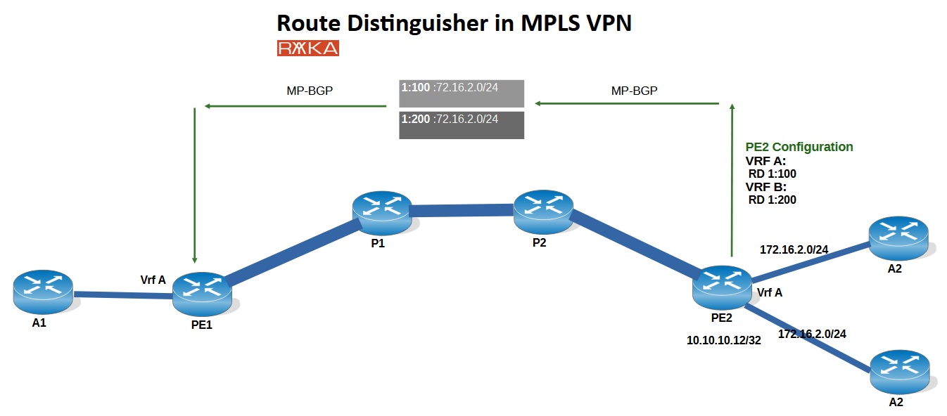
The prefix 172.16.2.0/24 is prepended with a Route Distinguisher (RD), specifically 1:100, which is configured in the VRF A on PE2. The RD is used to resolve ambiguity when different customers use overlapping IP address spaces — a common and supported scenario in MPLS VPNs.
In this example, both Customer A and Customer B are using the same IP prefix: 172.16.2.0/24. However, different Route Distinguishers (RDs) are configured on PE2 to keep these routes unique. Specifically, RD 1:100 is used for Customer A, and RD 1:200 for Customer B.
As a result, even though the IP prefixes are identical, the routes remain distinct when advertised through MP-BGP. The RD value effectively creates unique VPNv4 routes, preventing any overlap or conflict between the two customers in the service provider’s BGP table.
Each RD is unique per VRF on each PE router. It is locally significant, meaning that the same VRF can have a different RD on different PE routers. However, in practice, it’s common to use the same RD across PEs for the same VRF to simplify management and troubleshooting.
Router Traget (RT)
In addition to the RD, an RT (Route Target) is also attached to the advertised route. RTs play a critical role in MPLS VPN architecture and will be covered in more detail in the next dedicated lesson.
For now, here’s a brief overview of how RTs function:
Each VRF is typically configured with at least two RTs: an export RT and an import RT.
The export RT is attached to customer routes and advertised via MP-BGP to other PE routers.
When a PE router receives a route, it checks whether the RT attached to it matches any of its import RTs configured in any VRF.
If a match is found, the route is imported into the corresponding VRF on the receiving PE router.
This RT-based mechanism allows flexible and scalable control over which VPN routes are shared between which sites. This mechanism allows us to build various customer topologies based on specific requirements, such as full-mesh or hub-and-spoke configurations.
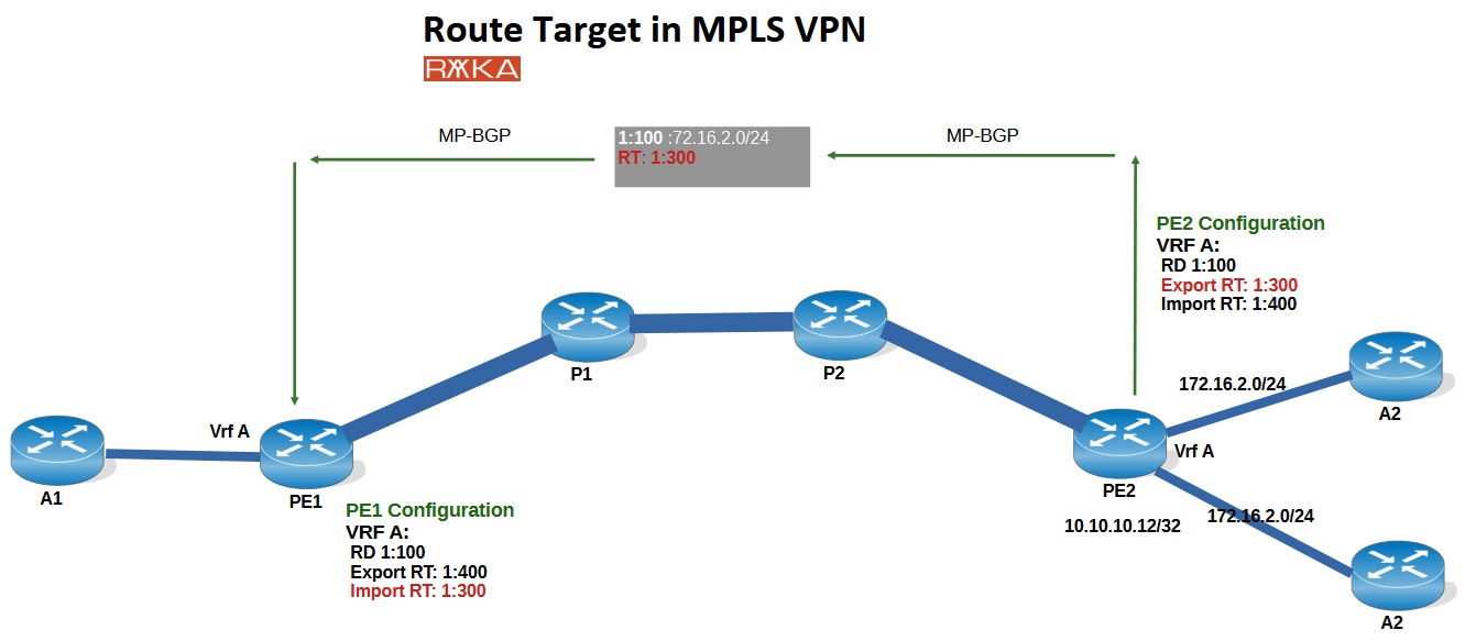
To better understand how Route Targets (RTs) work, let’s look at the configuration on PE2. In VRF A, Export RT is set to 1:300 and Import RT is set to 1:400. The Export RT is the value that is actually attached to the route and advertised via MP-BGP.
When this route reaches PE1, it will be imported into VRF A only if the RT attached to the route (1:300) matches the Import RT configured under VRF A on PE1. In this example, PE1 is configured with Import RT 1:300, allowing it to accept the route from PE2.
Note that in this setup, the Export and Import RT values are configured in opposite directions on PE1 and PE2. This deliberate configuration helps to clearly demonstrate how RTs control route distribution between VRFs across PE routers in an MPLS VPN.
VPN Label
Finally, the VPN label is advertised along with each route via MP-BGP between the PE routers. In this specific example, for the prefix 172.16.2.0/24 located in VRF A on PE2, VPN label 22 is generated and advertised to other PE routers through MP-BGP.
In other words, each PE router generates a VPN label for every customer prefix that it learns directly fro the customer and distributes this information to other PE routers using MP-BGP. These remote PE routers will then use the received VPN label as the inner label when sending customer traffic destined for that prefix.
This inner label allows the receiving PE router to correctly identify the destination VRF, ensuring the traffic is delivered to the appropriate customer. Without this mechanism, the PE router wouldn’t be able to distinguish between different customers using overlapping IP address spaces, which is common in MPLS VPN environments.
By using the command „show bgp vpnv4 unicast vrf A 172.16.2.2“ on PE1, you can view the Route Target (RT) and the VPN label that were advertised via MP-BGP from the PE2 router for the specific prefix 172.16.2.0/24 in VRF A.
PE1#show bgp vpnv4 unicast vrf A 172.16.2.2
BGP routing table entry for 1:100:172.16.2.0/24, version 6
Paths: (1 available, best #1, table A)
  Not advertised to any peer
  Refresh Epoch 1
  Local
    10.10.10.12 (metric 31) from 10.10.10.12 (10.10.10.12)
      Origin incomplete, metric 0, localpref 100, valid, internal, best
      Extended Community: RT:1:100
      mpls labels in/out nolabel/22
      rx pathid: 0, tx pathid: 0x0
The command „show bgp vpnv4 unicast vrf A labels“ displays all VPN labels advertised and received for all prefixes within VRF A. In the output, the label before the slash ( / ) represents the data plane incoming label which is generated and advertised by local PE router. The label after the slash indicates the data plane outgoing label which is generated and advertise with remote PE router..
PE1#show bgp vpnv4 unicast vrf A labels
   Network          Next Hop      In label/Out label
Route Distinguisher: 1:100 (A)
   172.16.1.0/24    0.0.0.0         22/nolabel(A)
   172.16.2.0/24    10.10.10.12     nolabel/22