MPLS TTL propagation, enabled by default, allows the TTL value to be copied between the IP and MPLS networks. As a result, when performing a traceroute from an IP network through an MPLS network, all P routers are transparently visible. However, by disabling TTL propagation, we can prevent MPLS P routers from being exposed to IP customers, effectively hiding them from view.
How TTL Propagation works
To better understand how MPLS TTL propagation works and how disabling it can hide the MPLS core, let’s examine this topology and discuss what happens in the background.
This topology is based on the one we prepared in the previous lesson, where OSPF and LDP are deployed in the service provider network. However, I have now added customer edge (CE) routers, CE1 and CE2, which are connected to provider edge (PE) routers, PE1 and PE2.
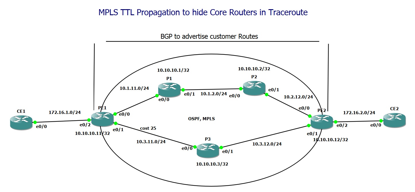
To enable connectivity between CE1 and CE2, I have configured BGP between PE1 and PE2 to advertise the customer networks (172.16.1.0/24 and 172.16.2.0/24). This exchange occurs directly between the PE routers, without involving the MPLS core routers.
How is customer traffic forwarded through the P routers without them knowing the customer routes? While this is not the focus of this lesson, it’s important to note that customer traffic is tunneled between PE1 and PE2 through an MPLS Tunnel (LSP), allowing the P routers to forward traffic based on the MPLS labels rather than the customer IP routes.
# PE1
hostname PE1
!
ip cef
!
mpls label protocol ldp
!
interface Loopback0
 ip address 10.10.10.11 255.255.255.255
!
interface Ethernet0/0
 ip address 10.1.11.11 255.255.255.0
 mpls ip
!
interface Ethernet0/1
 ip address 10.3.11.11 255.255.255.0
 ip ospf cost 25
 mpls ip
!
interface Ethernet0/2
 ip address 172.16.1.11 255.255.255.0
!
router ospf 1
 router-id 11.11.11.11
 network 10.0.0.0 0.255.255.255 area 0
!
router bgp 65001
 bgp router-id 11.11.11.11
 bgp log-neighbor-changes
 network 172.16.1.0 mask 255.255.255.0
 neighbor 10.10.10.12 remote-as 65001
 neighbor 10.10.10.12 update-source Loopback0
 neighbor 10.10.10.12 next-hop-self
!
mpls ldp router-id Loopback0
# PE2
hostname PE2
!
ip cef
!
mpls label protocol ldp
!
interface Loopback0
 ip address 10.10.10.12 255.255.255.255
!
interface Ethernet0/0
 ip address 10.2.12.12 255.255.255.0
 mpls ip
!
interface Ethernet0/1
 ip address 10.3.12.12 255.255.255.0
 mpls ip
!
interface Ethernet0/2
 ip address 172.16.2.12 255.255.255.0
!
router ospf 1
 router-id 12.12.12.12
 network 10.0.0.0 0.255.255.255 area 0
!
router bgp 65001
 bgp router-id 12.12.12.12
 bgp log-neighbor-changes
 network 172.16.2.0 mask 255.255.255.0
 neighbor 10.10.10.11 remote-as 65001
 neighbor 10.10.10.11 update-source Loopback0
 neighbor 10.10.10.11 next-hop-self
!
mpls ldp router-id Loopback0
# P1
hostname P1
!
ip cef
!
mpls label protocol ldp
!
interface Loopback0
 ip address 10.10.10.1 255.255.255.255
!
interface Ethernet0/0
 ip address 10.1.11.1 255.255.255.0
 mpls ip
!
interface Ethernet0/1
 ip address 10.1.2.1 255.255.255.0
 mpls ip
!
router ospf 1
 router-id 1.1.1.1
 network 10.0.0.0 0.255.255.255 area 0
!
mpls ldp router-id Loopback0
hostname CE1
!
interface Ethernet0/0
 ip address 172.16.1.1 255.255.255.0
!
ip route 0.0.0.0 0.0.0.0 172.16.1.11
Traceroute with TTL Propagation Enabled (default)
Now we are ready to run a traceroute between the CE routers and also between the PE routers. As you can see in the output, by default, the core routers are visible to traceroute because TTL propagation is enabled by default.
CE1#traceroute 172.16.2.2
Type escape sequence to abort.
Tracing the route to 172.16.2.2
VRF info: (vrf in name/id, vrf out name/id)
  1 172.16.1.11 5 msec 6 msec 6 msec
  2 10.1.11.1 [MPLS: Label 22 Exp 0] 4 msec 4 msec 5 msec
  3  *  *  *
  4 10.2.12.12 2 msec 7 msec 5 msec
  5 172.16.2.2 3 msec 2 msec 1 msec
CE1#
PE1(config)#do traceroute 10.10.10.12 sou 10.10.10.11
Type escape sequence to abort.
Tracing the route to 10.10.10.12
VRF info: (vrf in name/id, vrf out name/id)
  1 10.1.11.1 [MPLS: Label 22 Exp 0] 5 msec 7 msec 4 msec
  2 10.1.2.2 [MPLS: Label 20 Exp 0] 5 msec 5 msec 5 msec
  3 10.2.12.12 5 msec 4 msec 4 msec
PE1(config)#
what does MPLS TTL Propagation mean?
So, what does TTL propagation mean? When an IP packet from CE1 reaches PE1 (the edge of the MPLS backbone), the TTL value from the IP header is copied into the TTL field of the MPLS label. When the MPLS packet reaches the MPLS edge at PE2, the TTL value from the MPLS label is copied back into the IP header’s TTL field.
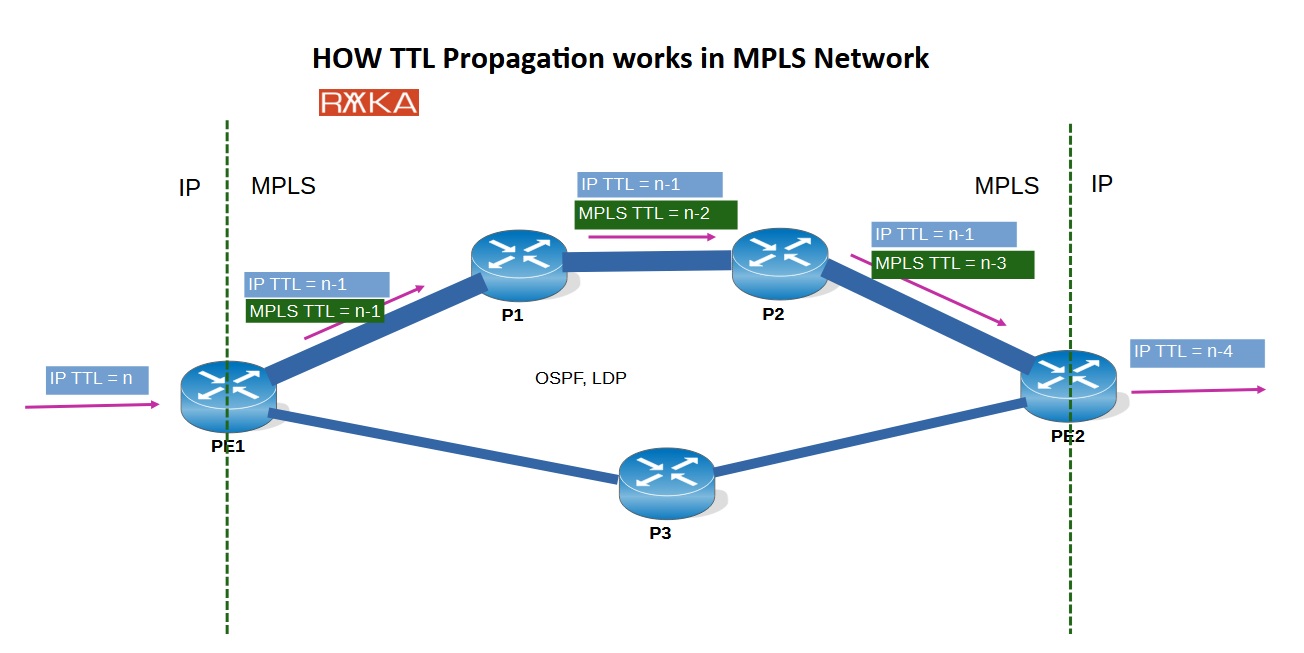
From the perspective of traceroute, there is no difference whether this is an IP backbone, an MPLS backbone, or a mixture of both, since the TTL is consistently propagated across all hops.
Note that, for simplicity, we have ignored penultimate hop popping (PHP) in this example. However, in reality, the MPLS label is removed one hop before the last MPLS hop, and at that point, the TTL field in the IP header is processed accordingly.
Disable TTL Propagation
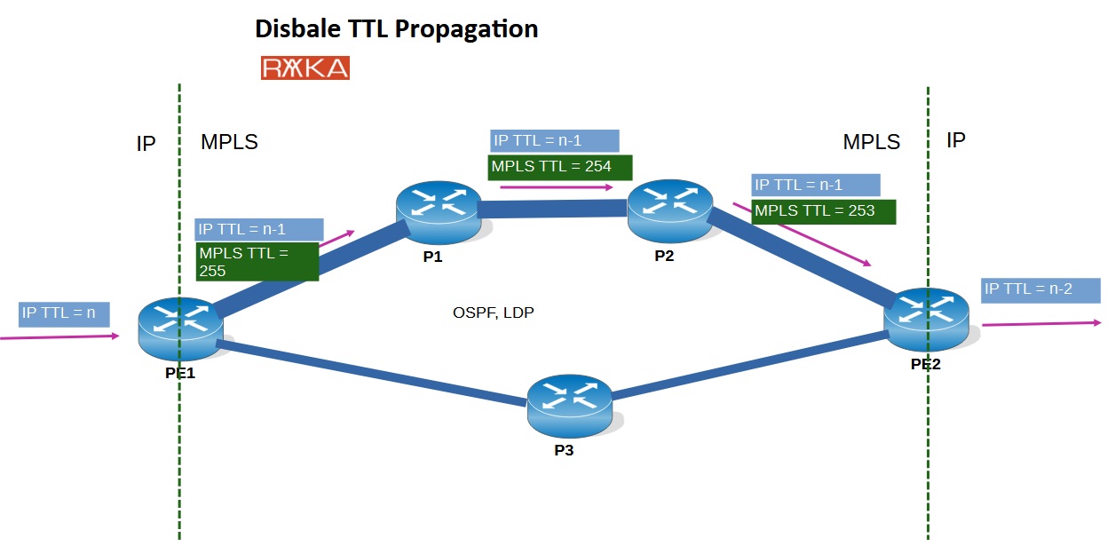
When no
mpls ip propagate-ttl is configured on the ingress Label Edge Router (LER), the TTL from the IP header is not copied to the MPLS label. Instead, the label is assigned a high TTL (typically 255), ensuring it does not expire within the MPLS core. As a result, MPLS core routers do not decrement the TTL and remain hidden from the traceroute output. Only the ingress and egress routers will be visible, effectively concealing the MPLS core.
Now, let’s disable TTL propagation on the PE1 router and run traceroute again from CE1 to CE2 and PE1 to PE2.
CE1#traceroute 172.16.2.2 Type escape sequence to abort. Tracing the route to 172.16.2.2 VRF info: (vrf in name/id, vrf out name/id) 1 172.16.1.11 2 msec 4 msec 5 msec 2 10.2.12.12 1 msec 4 msec 5 msec 3 172.16.2.2 6 msec 5 msec 5 msec CE1#
PE1(config)#do traceroute 10.10.10.12 sou 10.10.10.11 Type escape sequence to abort. Tracing the route to 10.10.10.12 VRF info: (vrf in name/id, vrf out name/id) 1 10.2.12.12 5 msec 6 msec 5 msec PE1(config)#
As you can see in the results, all P routers in the path, including P1 and P2, are now hidden. Only the first and last PE routers in the MPLS network are displayed, effectively concealing the MPLS core.
„forward“ and „local“ options in „no mpls ip propagate-ttl“ command
Sometimes, we need to disable TTL propagation only for traffic received from customers and forwarded through the MPLS network while still allowing traceroute within the MPLS network for troubleshooting purposes.
no mpls ip propagate-ttl forwarded
The no mpls ip propagate-ttl forwarded command disables TTL propagation only for forwarded traffic, while locally originated traffic (such as traceroute probes generated by the router itself) still propagates TTL. As a result, locally generated traceroute can still detect and display P routers within the MPLS network.
CE1#traceroute 172.16.2.2
Type escape sequence to abort.
Tracing the route to 172.16.2.2
VRF info: (vrf in name/id, vrf out name/id)
  1 172.16.1.11 5 msec 6 msec 5 msec
  2 10.2.12.12 5 msec 5 msec 5 msec
  3 172.16.2.2 5 msec 5 msec 5 msec
CE1#
PE1(config)#do traceroute 10.10.10.12 sou 10.10.10.11
Type escape sequence to abort.
Tracing the route to 10.10.10.12
VRF info: (vrf in name/id, vrf out name/id)
  1 10.1.11.1 [MPLS: Label 22 Exp 0] 5 msec 5 msec 6 msec
  2 10.1.2.2 [MPLS: Label 20 Exp 0] 5 msec 4 msec 5 msec
  3 10.2.12.12 5 msec 4 msec 4 msec
PE1(config)#
no mpls ip propagate-ttl local
This command also has the local option, as in no mpls ip propagate-ttl local, which behaves in the opposite manner. This means TTL will not be propagated for local traffic, so traceroute probes generated by the router itself will not reveal P routers. However, TTL propagation still applies for forwarded traffic, meaning customer traffic will continue to see the P routers.
CE1#traceroute 172.16.2.2
Type escape sequence to abort.
Tracing the route to 172.16.2.2
VRF info: (vrf in name/id, vrf out name/id)
  1 172.16.1.11 1 msec 5 msec 5 msec
  2 10.1.11.1 [MPLS: Label 22 Exp 0] 1 msec 1 msec 0 msec
  3  *  *  *
  4 10.2.12.12 3 msec 7 msec 6 msec
  5 172.16.2.2 1 msec 2 msec 0 msec
CE1#
PE1(config)#do traceroute 10.10.10.12 sou 10.10.10.11
Type escape sequence to abort.
Tracing the route to 10.10.10.12
VRF info: (vrf in name/id, vrf out name/id)
  1 10.2.12.12 1 msec 8 msec 5 msec
PE1(config)#