MPLS control plane and data plane are fundamental to understanding MPLS and its services like MPLS VPN, VPLS, and MPLS TE. The control plane is responsible for building the tables used for forwarding, while the data plane handles the actual packet forwarding based on these tables.
MPLS control plane and data plane
To better understand the concepts of the control plane and data plane, let’s first review them in the context of IP routing protocols, which we have been familiar with for a long time. Then, we will extend this knowledge to the MPLS network.
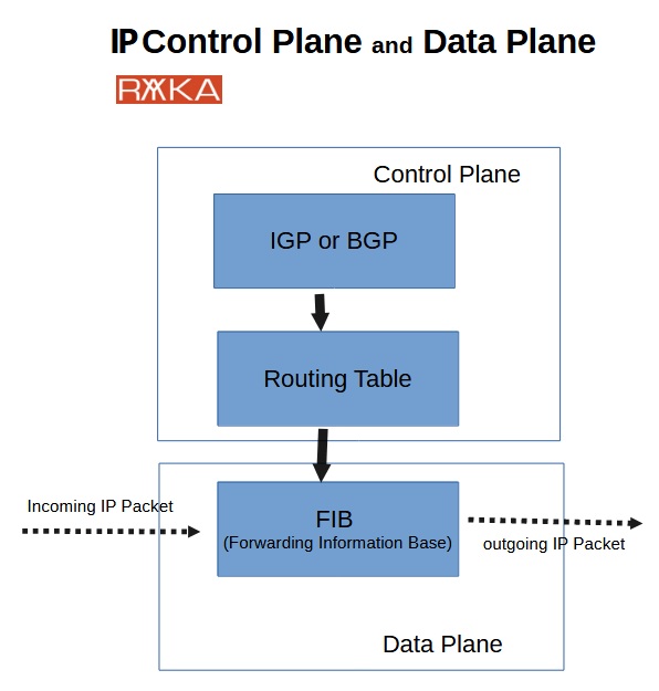
In an IP network, IGP or BGP routing protocols in control plane determine the best path to each destination and build the routing table based on this information. The routing table is then used to generate the CEF table (FIB) in the data plane, which is responsible for forwarding IP packets. In other words, when a router receives an IP packet, it checks the destination IP in the FIB table to determine the next hop, forwarding the packet until it reaches its destination.
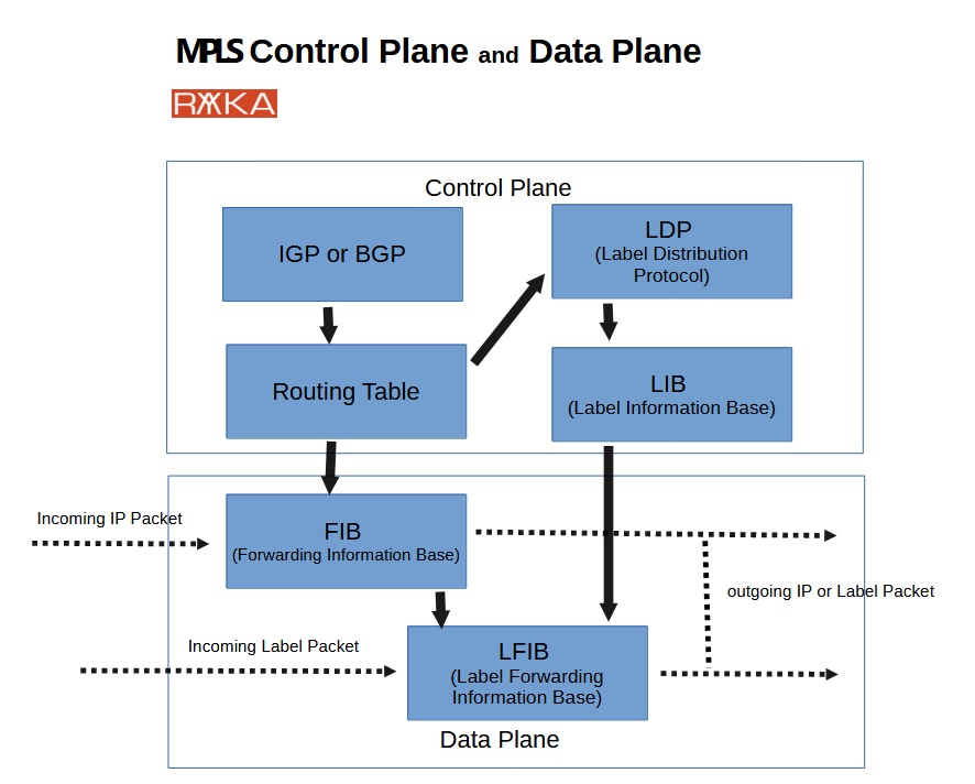
In contrast, MPLS is slightly more complex. In the control plane, the LDP protocol uses routing table information to distribute labels, creating the Label Information Base (LIB). The routing table and LIB are then used to generate the Forwarding Information Base (FIB) and Label Forwarding Information Base (LFIB) in the data plane, enabling the forwarding of both IP and labeled packets. The FIB is responsible for forwarding IP packets, while the LFIB handles labeled packet forwarding. Next, we will explore in detail how each of these tables is created in the control and data planes.
MPLS control plane
To begin discussing how MPLS operates at the control plane, consider the following service provider network topology utilizing MPLS technology. In this topology, there are two available paths between the PE routers:
The first path traverses two intermediate P routers, P1 and P2, offering higher bandwidth.
The second path goes through a single intermediate P router, P3, but with lower bandwidth.
For simplicity, let’s use a network connected to PE2 with the subnet 10.1.1.0/24 as our example destination. This subnet will serve as a reference to demonstrate how MPLS functions in both the control plane and data plane. The same process applies to all subnets within the service provider’s network.
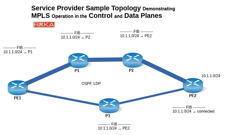
In the first step, we assume that IGP (OSPF as an example) is already running on this network, and the best paths have been established in the routing table. Based on this routing table, the FIB (Forwarding Information Base) table is created in the data plane, which is then used for IP traffic forwarding.
In this example, the FIB for each router, specifically for the destination 10.1.1.0/24, is displayed beside each router to show how traffic is forwarded to this destination across the network. As expected from PE1’s perspective, the path above with higher bandwidth is preferred for traffic destined for this specific subnet.
Now, let’s enable LDP (Label Distribution Protocol) as the MPLS protocol in this network. The question is: what exactly happens in each router to create the LFIB (Label Forwarding Information Base) and update the FIB (Forwarding Information Base), which are used for forwarding labeled and IP traffic?
Let’s list the steps involved, and discuss each of them one by one:
LDP Label binding
- Label Generation and LIB Table:
Each router generates a random label for each destination in its routing table and binds this label to the destination subnet in the LIB (Label Information Base) table. The LIB table, which resides in the control plane, stores all labels for each destination generated by the router and its neighboring routers.
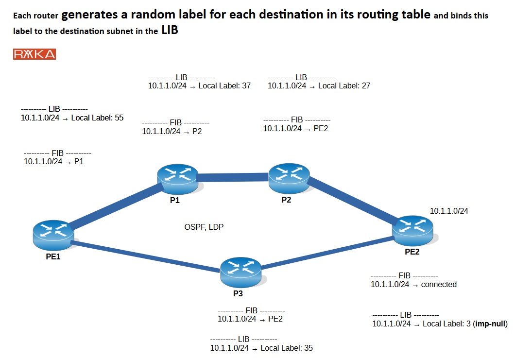
For the destination 10.1.1.0/24, router PE1 assigns label 55, router P1 assigns label 37, and router P2 assigns label 27. Router P1 then assigns label 35, and finally, router PE2 assigns label 3, which is a special label called implicit-null. We will discuss implicit-null label shortly.
There are two key points to note.
Note 1: The generated label is locally significant, meaning that different routers can generate the same label value independently without any relation between them.
Note 2: All routers generate the same label value 3 (implicit null) for all connected subnets. For example, PE1, with three connected subnets, generates label imp-null for all of those subnets. Similarly, P1, with three connected subnets, generates also label imp-null for all of its connected subnets. This is due to a process called Penultimate Hop Popping (PHP), which will be discussed shortly.
LDP Label advertisement
2. Label Advertisement:
Each router advertises the generated label for each destination to its upstream neighbors. For each destination subnet, the next-hop neighbor is the downstream neighbor, and all other neighbors are considered upstream routers. Each router adds labels generated by itself as well as labels generated by its neighbors to its LIB table.
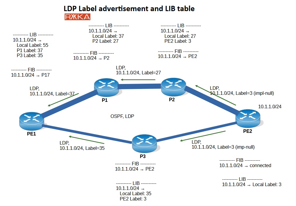
In this figure, router PE2 advertises its locally assigned label for the prefix 10.1.1.0/24 (implicit-null) to its upstream routers, P2 and P3. Router P2 then advertises its locally assigned label, 27, to its upstream neighbor, router P1. This process occurs simultaneously and independently on each router.
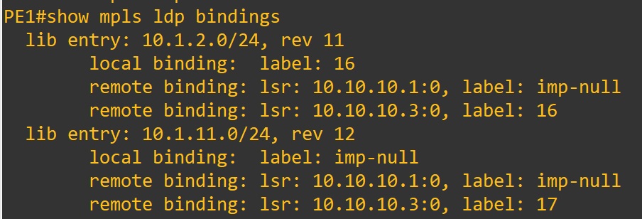
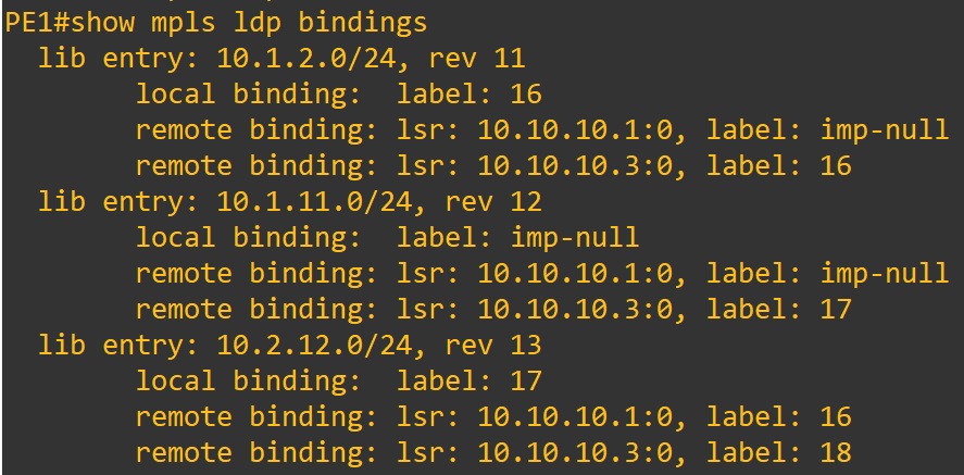
To better understand this concept, here is a section of a real LIB output from a router. It illustrates how each router maintains its locally assigned labels as well as the labels assigned by neighbors in the LIB table. You can also observe the implicit-null label in the table. In the next lesson, we will demonstrate MPLS in a practical scenario.
FIB Update process
3. FIB Table Construction:
As you’ve noticed, the LIB table stores both locally generated labels and labels assigned by neighboring routers for each subnet. At this stage, using both the LIB and FIB tables, the label generated by the next-hop router is added to the FIB table as the outgoing label for each destination subnet. The FIB table is then used to forward IP traffic efficiently.
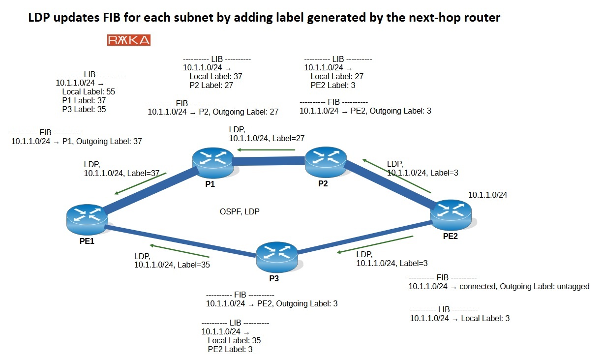
In our example, router PE1 updates its FIB table by adding the label generated by P1 (37) as the outgoing label for the subnet 10.1.1.0/24. P1 is already as the next-hop router for this subnet in the FIB table.
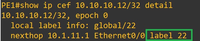
This is a real sample output of a router’s FIB table, which helps to better understand what happens in the background. We will demonstrate MPLS in practice in the next lesson.
how LFIB is created
4. LFIB Table Creation:
Finally, based on LIB and FIB tables, LFIB (Label Forwarding Information Base) is created. LFIB is responsible for forwarding labeled traffic, which we will discuss in the MPLS data plane shortly. Within LFIB, each subnet is associated with two labels:
Incoming label: locally generated label for that specific subnet.
Outgoing label: the label generated by the next-hop router for that specific subnet.
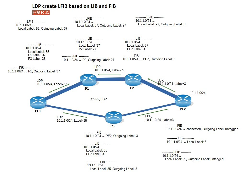
In our topology, taking router PE1 as an example, a new record is created in the LFIB table for the subnet 10.1.1.0/24. The local label (55) is assigned as the incoming label, while the label generated by the next-hop router (37) is added as the outgoing label. This process is repeated on all routers to update their respective LFIB tables.
This is a real sample output of a router’s LFIB table, which helps to better understand what happens in the background. We will demonstrate MPLS in practice in the next lesson.
MPLS data plane
Once the FIB (Forwarding Information Base) and LFIB (Label Forwarding Information Base) tables are updated and created on the routers, traffic forwarding will utilize these new forwarding tables. The FIB is responsible for forwarding incoming IP packets based on their destination IP addresses, while the LFIB is used to forward incoming labeled packets based on the associated label values.
In our topology, let’s assume that IP traffic is received on router PE1 destined for 10.1.1.1, which is connected to router PE2. The traffic will be forwarded using the FIB since the incoming traffic is an IP packet, not a labeled packet. According to the FIB, the packet will be forwarded to P1 with an outgoing label of 37, which is the local label assigned by P1 for this subnet.
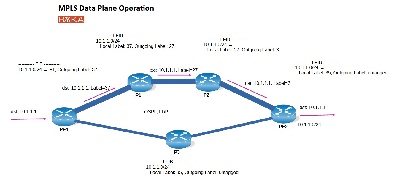
Router P1, receiving labeled traffic, will use the LFIB to forward the traffic. The incoming label (37) is local label for this specifc destination, and it will be swapped with the outgoing label (27) assigned, assigned by the next-hop router.
This process continues at router P2. Router P2 also receives labeled traffic, so it uses the LFIB to forward the traffic. The incoming label (27) is local label for this specifc destination destination, and it will be swapped with the label assigned by the next-hop router, which is 3 (implicit-null).
As you can see, each router receives traffic with a local label and forwards it with the label assigned by the next-hop router.
MPLS PHP (Penultimate Hop Popping)
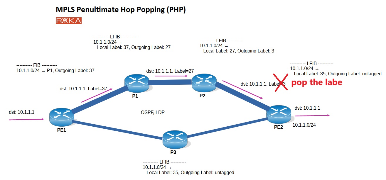
It’s important to note that in an MPLS network, the router just before the last router always forwards traffic with label 3 (implicit-null) to the final router for a destination connected to it. This is because routers in MPLS always assign label 3 (implicit-null) for directly connected subnets.
Now it’s important to understand that implicit-null is actually a signal to pop the label. In other words, the traffic will not be swapped with label 3 in the router just before the last router; instead, the label will be popped. This process is called Penultimate Hop Popping (PHP), and its main goal is to improve efficiency. By popping the label one router before the last router, the last router no longer needs to process this label, thus reducing the processing load and simplifying the forwarding process.
what is special with MPLS
Now that we understand how MPLS operates in both the control plane and the data plane, let’s undreatnd why MPLS is so practical. What are the key components of MPLS that provide the advantages of MPLS services?
What I personally see as the real advantage of MPLS comes down to two key components.
First, MPLS provides a tunneling mechanism similar to GRE, but instead of using encapsulation, it relies on labels. This means that customer traffic can be tunneled over an MPLS network without the need to advertise customer routes or information within the service provider’s MPLS core. MPLS-based tunne, established through labels, are known as Label Switched Path (LSP).
| Advantage | Description | Benefit |
|---|---|---|
| 1. Creating Tunnels | MPLS uses labels to establish Label Switched Paths (LSPs) for tunneling customer traffic. | Efficiently isolates customer traffic without advertising their routes in the provider’s core. |
| 2. Label Meaning | Labels carry additional meaning beyond tunneling, supporting multiple stacked labels. | Enables advanced functionality, such as: - Customer Differentiation (e.g., MPLS VPN, VPLS) - Path Distinction (e.g., Traffic Engineering). |
The question arises: why not use other existing tunneling mechanisms like GRE instead of MPLS? This brings us to another key advantage of MPLS.
Unlike GRE, MPLS labels can carry additional meaning beyond simply establishing tunnels. As we will see throughout this course, a packet can have more than one label, and these labels can serve purposes beyond just creating Label Switched Paths (LSPs). For example, labels are used to differentiate customers in MPLS VPN and VPLS solutions or to distinguish paths in MPLS Traffic Engineering.
In other words, MPLS services use different types of labels. While one label is used to create an LSP tunnel, additional labels are advertised to differentiate customers, paths, and services, enabling advanced MPLS functionalities.