MPLS central services VPN, also known as MPLS VPN shared services, is a topology where multiple customer VPNs securely access shared services like voice gateways or Internet access, while traffic isolation is maintained through route-target filtering and route leaking.
Central services VPN Fundamental
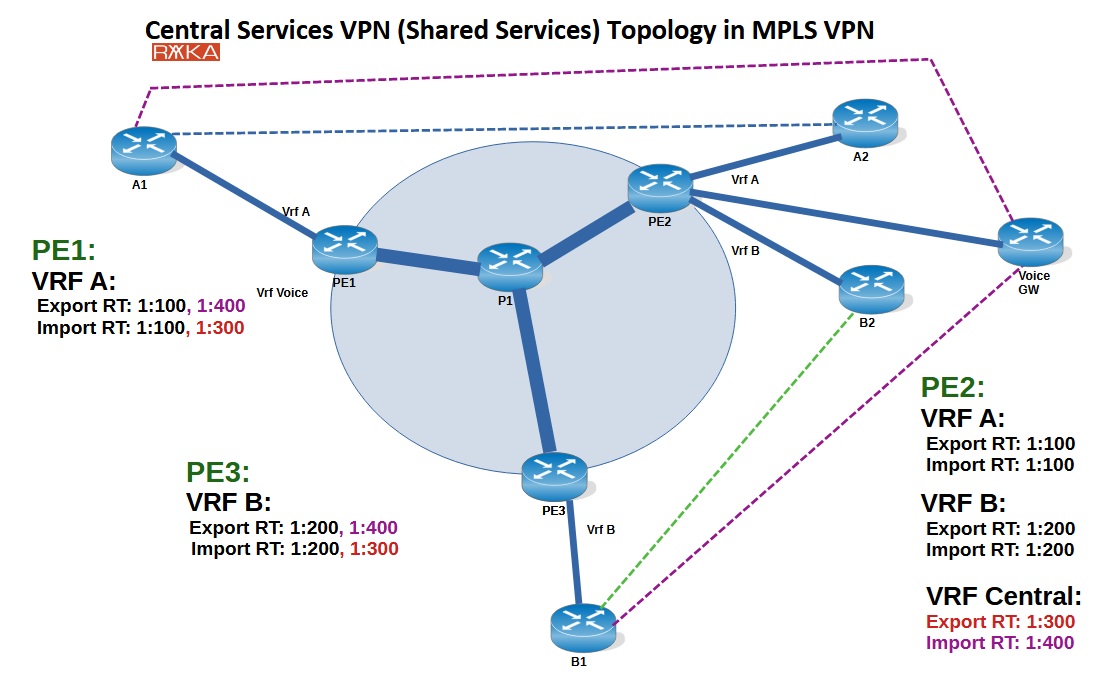
This is an example of a central services VPN (or shared services VPN) topology in an MPLS backbone, where multiple customer VPNs (VRF A and VRF B) maintain isolated routing domains while sharing access to a common service, such as a voice gateway, via a central VRF.
Route-target (RT) import/export policies enable selective route leaking: customer VRFs import routes from the central VRF (RT 1:300), and the central VRF imports routes from both customer VRFs (RTs 1:400). This ensures that only designated sites (e.g., central offices) from each customer can reach the shared service without exposing their entire network.
Central Service Configuration Example
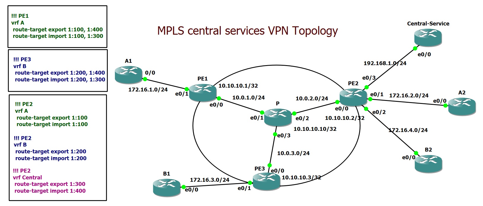
This topology is implemented using GNS3 to simulate a service provider MPLS environment. Within the provider network, OSPF and MPLS are configured within the provider network. Three VRFs are defined: VRF A, VRF B, and VRF Central. Interfaces connected to customer sites are assigned to their respective VRFs. MP-BGP with the VPNv4 address family is configured between the PE routers, and the routes from each customer VRF are redistributed into MP-BGP for advertisement across the MPLS core.
Route-targets are configured as follows: RT 1:100 is used for both import and export in VRF A, and RT 1:200 for VRF B. VRF Central exports RT 1:300, which is imported by any customer VRF requiring access to shared services. Additionally, RT 1:400 is exported by the customer VRFs (VRF A and B) to advertise their routes to the central VRF, which imports RT 1:400.
hostname PE1
!
ip vrf A
 rd 1:100
 route-target export 1:100
 route-target export 1:400
 route-target import 1:100
 route-target import 1:300
!
ip cef
!
mpls label protocol ldp
!
interface Loopback0
 ip address 10.10.10.1 255.255.255.255
!
interface Ethernet0/0
 ip address 10.0.1.1 255.255.255.0
 mpls ip
!
interface Ethernet0/1
 ip vrf forwarding A
 ip address 172.16.1.1 255.255.255.0
!
router ospf 1
 network 10.0.0.0 0.255.255.255 area 0
!
router bgp 65001
 bgp log-neighbor-changes
 neighbor 10.10.10.2 remote-as 65001
 neighbor 10.10.10.2 update-source Loopback0
 neighbor 10.10.10.3 remote-as 65001
 neighbor 10.10.10.3 update-source Loopback0
 !
 address-family vpnv4
  neighbor 10.10.10.2 activate
  neighbor 10.10.10.2 send-community both
  neighbor 10.10.10.2 next-hop-self
  neighbor 10.10.10.3 activate
  neighbor 10.10.10.3 send-community both
  neighbor 10.10.10.3 next-hop-self
 exit-address-family
 !
 address-family ipv4 vrf A
  redistribute connected
 exit-address-family
!
mpls ldp router-id Loopback0
hostname PE2
!
ip vrf A
 rd 1:100
 route-target export 1:100
 route-target import 1:100
!
ip vrf B
 rd 1:200
 route-target export 1:200
 route-target import 1:200
!
ip vrf Central
 rd 1:300
 route-target export 1:300
 route-target import 1:400
!
ip cef
!
mpls label protocol ldp
!
interface Loopback0
 ip address 10.10.10.2 255.255.255.255
!
interface Ethernet0/0
 ip address 10.0.2.2 255.255.255.0
 mpls ip
!
interface Ethernet0/1
 ip vrf forwarding A
 ip address 172.16.2.1 255.255.255.0
!
interface Ethernet0/2
 ip vrf forwarding B
 ip address 172.16.4.1 255.255.255.0
!
interface Ethernet0/3
 ip vrf forwarding Central
 ip address 192.168.1.1 255.255.255.0
!
router ospf 1
 network 10.0.0.0 0.255.255.255 area 0
!
router bgp 65001
 bgp log-neighbor-changes
 neighbor 10.10.10.1 remote-as 65001
 neighbor 10.10.10.1 update-source Loopback0
 neighbor 10.10.10.3 remote-as 65001
 neighbor 10.10.10.3 update-source Loopback0
 !
 address-family vpnv4
  neighbor 10.10.10.1 activate
  neighbor 10.10.10.1 send-community both
  neighbor 10.10.10.1 next-hop-self
  neighbor 10.10.10.3 activate
  neighbor 10.10.10.3 send-community both
  neighbor 10.10.10.3 next-hop-self
 exit-address-family
 !
 address-family ipv4 vrf A
  redistribute connected
 exit-address-family
 !
 address-family ipv4 vrf B
  redistribute connected
 exit-address-family
 !
 address-family ipv4 vrf Central
  redistribute connected
 exit-address-family
!
mpls ldp router-id Loopback0
hostname PE3
!
ip vrf B
 rd 1:200
 route-target export 1:200
 route-target export 1:400
 route-target import 1:200
 route-target import 1:300
!
ip cef
!
mpls label protocol ldp
!
interface Loopback0
 ip address 10.10.10.3 255.255.255.255
!
interface Ethernet0/0
 ip address 10.0.3.3 255.255.255.0
 mpls ip
!
interface Ethernet0/1
 ip vrf forwarding B
 ip address 172.16.3.1 255.255.255.0
!
router ospf 1
 network 10.0.0.0 0.255.255.255 area 0
!
router bgp 65001
 bgp log-neighbor-changes
 neighbor 10.10.10.1 remote-as 65001
 neighbor 10.10.10.1 update-source Loopback0
 neighbor 10.10.10.2 remote-as 65001
 neighbor 10.10.10.2 update-source Loopback0
 !
 address-family vpnv4
  neighbor 10.10.10.1 activate
  neighbor 10.10.10.1 send-community both
  neighbor 10.10.10.1 next-hop-self
  neighbor 10.10.10.2 activate
  neighbor 10.10.10.2 send-community both
  neighbor 10.10.10.2 next-hop-self
 exit-address-family
 !
 address-family ipv4 vrf B
  redistribute connected
 exit-address-family
!
mpls ldp router-id Loopback0
hostname P
!
ip cef
!
mpls label protocol ldp
!
interface Loopback0
 ip address 10.10.10.10 255.255.255.255
!
interface Ethernet0/0
 no ip address
 shutdown
!
interface Ethernet0/1
 ip address 10.0.1.10 255.255.255.0
 mpls ip
!
interface Ethernet0/2
 ip address 10.0.2.10 255.255.255.0
 mpls ip
!
interface Ethernet0/3
 ip address 10.0.3.10 255.255.255.0
 mpls ip
!
router ospf 1
 network 10.0.0.0 0.255.255.255 area 0
!
mpls ldp router-id Loopback0
Troubleshooting MPLS Central Services VPN
Verification confirms the setup is working as expected. BGP VPNv4 tables on PE1 and PE3 show the expected routes for customer and shared service prefixes.
PE1#show bgp vpnv4 unicast vrf A
BGP table version is 13, local router ID is 10.10.10.1
Status codes: s suppressed, d damped, h history, * valid, > best, i - internal,
              r RIB-failure, S Stale, m multipath, b backup-path, f RT-Filter,
              x best-external, a additional-path, c RIB-compressed,
Origin codes: i - IGP, e - EGP, ? - incomplete
RPKI validation codes: V valid, I invalid, N Not found

     Network          Next Hop            Metric LocPrf Weight Path
Route Distinguisher: 1:100 (default for vrf A)
 *>  172.16.1.0/24    0.0.0.0                  0         32768 ?
 *>i 172.16.2.0/24    10.10.10.2               0    100      0 ?
 *>i 192.168.1.0      10.10.10.2               0    100      0 ?
PE1#show bgp vpnv4 unicast vrf A labels
   Network          Next Hop      In label/Out label
Route Distinguisher: 1:100 (A)
   172.16.1.0/24    0.0.0.0         22/nolabel(A)
   172.16.2.0/24    10.10.10.2      nolabel/22
   192.168.1.0      10.10.10.2      nolabel/23
PE3(config)#do sh bgp vpnv4 unicast vrf B
BGP table version is 11, local router ID is 10.10.10.3
Status codes: s suppressed, d damped, h history, * valid, > best, i - internal,
              r RIB-failure, S Stale, m multipath, b backup-path, f RT-Filter,
              x best-external, a additional-path, c RIB-compressed,
Origin codes: i - IGP, e - EGP, ? - incomplete
RPKI validation codes: V valid, I invalid, N Not found

     Network          Next Hop            Metric LocPrf Weight Path
Route Distinguisher: 1:200 (default for vrf B)
 *>  172.16.3.0/24    0.0.0.0                  0         32768 ?
 *>i 172.16.4.0/24    10.10.10.2               0    100      0 ?
 *>i 192.168.1.0      10.10.10.2               0    100      0 ?
PE3(config)#do sh bgp vpnv4 unicast vrf B labels
   Network          Next Hop      In label/Out label
Route Distinguisher: 1:200 (B)
   172.16.3.0/24    0.0.0.0         16/nolabel(B)
   172.16.4.0/24    10.10.10.2      nolabel/16
   192.168.1.0      10.10.10.2      nolabel/23
PE2(config)#do sh bgp vpnv4 unicast vrf Central
BGP table version is 14, local router ID is 10.10.10.2
Status codes: s suppressed, d damped, h history, * valid, > best, i - internal,
              r RIB-failure, S Stale, m multipath, b backup-path, f RT-Filter,
              x best-external, a additional-path, c RIB-compressed,
Origin codes: i - IGP, e - EGP, ? - incomplete
RPKI validation codes: V valid, I invalid, N Not found

     Network          Next Hop            Metric LocPrf Weight Path
Route Distinguisher: 1:300 (default for vrf Central)
 *>i 172.16.1.0/24    10.10.10.1               0    100      0 ?
 *>i 172.16.3.0/24    10.10.10.3               0    100      0 ?
 *>  192.168.1.0      0.0.0.0                  0         32768 ?
Traceroute tests from customer sites A1 and B1 to the central service IP (192.168.1.2) demonstrate correct MPLS label usage and successful packet delivery. Conversely, traffic from sites A2 and B2 to the shared service fails, confirming proper segmentation. This configuration allows secure and controlled access to shared services while maintaining traffic isolation between different customer VPNs.
A1#traceroute 172.16.2.2
Type escape sequence to abort.
Tracing the route to 172.16.2.2
VRF info: (vrf in name/id, vrf out name/id)
  1 172.16.1.1 1 msec 6 msec 6 msec
  2 10.0.1.10 [MPLS: Labels 20/22 Exp 0] 1 msec 1 msec 1 msec
  3 172.16.2.1 0 msec 0 msec 0 msec
  4 172.16.2.2 1 msec 0 msec 0 msec
A1#traceroute 192.168.1.2
Type escape sequence to abort.
Tracing the route to 192.168.1.2
VRF info: (vrf in name/id, vrf out name/id)
  1 172.16.1.1 2 msec 5 msec 6 msec
  2 10.0.1.10 [MPLS: Labels 20/23 Exp 0] 2 msec 1 msec 1 msec
  3 192.168.1.1 0 msec 0 msec 1 msec
  4 192.168.1.2 1 msec 0 msec 1 msec
A2#traceroute 192.168.1.2
Type escape sequence to abort.
Tracing the route to 192.168.1.2
VRF info: (vrf in name/id, vrf out name/id)
  1 172.16.2.1 5 msec 6 msec 4 msec
  2 172.16.2.1 !H  !H  !H
B1#traceroute 172.16.4.2
Type escape sequence to abort.
Tracing the route to 172.16.4.2
VRF info: (vrf in name/id, vrf out name/id)
  1 172.16.3.1 1 msec 5 msec 5 msec
  2 10.0.3.10 [MPLS: Labels 20/16 Exp 0] 1 msec 1 msec 0 msec
  3 172.16.4.1 1 msec 0 msec 1 msec
  4 172.16.4.2 0 msec 1 msec 1 msec
B1#traceroute 192.168.1.2
Type escape sequence to abort.
Tracing the route to 192.168.1.2
VRF info: (vrf in name/id, vrf out name/id)
  1 172.16.3.1 3 msec 5 msec 6 msec
  2 10.0.3.10 [MPLS: Labels 20/23 Exp 0] 5 msec 4 msec 5 msec
  3 192.168.1.1 5 msec 5 msec 5 msec
  4 192.168.1.2 5 msec 5 msec 1 msec
B2#traceroute 192.168.1.2
Type escape sequence to abort.
Tracing the route to 192.168.1.2
VRF info: (vrf in name/id, vrf out name/id)
  1 172.16.4.1 5 msec 4 msec 5 msec
  2 172.16.4.1 !H  !H  !H