Cisco MPLS configuration is the focus of this section, exploring LDP protocol and LIB in control plane, FIB and LFIB in data plane, while also tracing packets and analyzing the MPLS label format structure.
Cisco MPLS Configuration
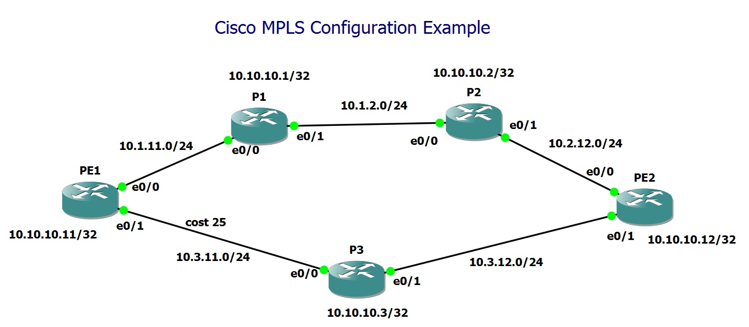
This topology is designed to demonstrate the implementation of MPLS using the LDP protocol. It consists of two PE routers, PE1 and PE2, which are connected through two distinct paths via three P routers: P1, P2, and P3.
The network is addressed using the 10.0.0.0/8 subnet. The second and third octets in each link’s subnet indicate the router numbers at both ends of the link. The P routers are numbered as follows: P1 = 1, P2 = 2, and P3 = 3. Similarly, the PE routers are numbered as PE1 = 11 and PE2 = 12.
For example, the subnet 10.1.11.0/24 represents the link between P1 and PE1. The last octet in each IP address corresponds to the router number. Thus, on this link, P1 is assigned 10.1.11.1/24, while PE1 is assigned 10.1.11.11/24.
Each router also has a loopback interface assigned in the format 10.10.10.X/32, where X corresponds to the router number. For example, P1 has 10.10.10.1/32, and PE1 has 10.10.10.11/32.”
MPLS Configuration Steps
To configure MPLS, we first assume that an IGP, such as OSPF, is already set up and that network connectivity is functioning correctly.
PE1#show running-config | sec router ospf
router ospf 1
 router-id 11.11.11.11
 network 10.0.0.0 0.255.255.255 area 0
PE1#show ip ospf neighbor

Neighbor ID     Pri   State           Dead Time   Address         Interface
3.3.3.3           1   FULL/BDR        00:00:33    10.3.11.3       Ethernet0/1
1.1.1.1           1   FULL/BDR        00:00:37    10.1.11.1       Ethernet0/0
PE1#ping 10.10.10.12 source 10.10.10.11
Type escape sequence to abort.
Sending 5, 100-byte ICMP Echos to 10.10.10.12, timeout is 2 seconds:
Packet sent with a source address of 10.10.10.11
!!!!!
Success rate is 100 percent (5/5), round-trip min/avg/max = 4/4/6 ms
Note that in this specific example, I have increased the cost between routers PE1 and P3 to ensure that the above path becomes the preferred path from an OSPF perspective.
Next, we enable MPLS globally, configure LDP as the label distribution protocol, and ensure that MPLS is explicitly enabled on each relevant interface. Note that MPLS is not supported on loopback interfaces.
We then configure the LDP Router ID. By default, LDP selects the highest IP address from a loopback or active interface as its Router ID. However, you can manually specify a loopback interface as the Router ID. It is important to ensure that the Router ID is reachable between neighboring routers, as LDP establishes a TCP connection over port 646.
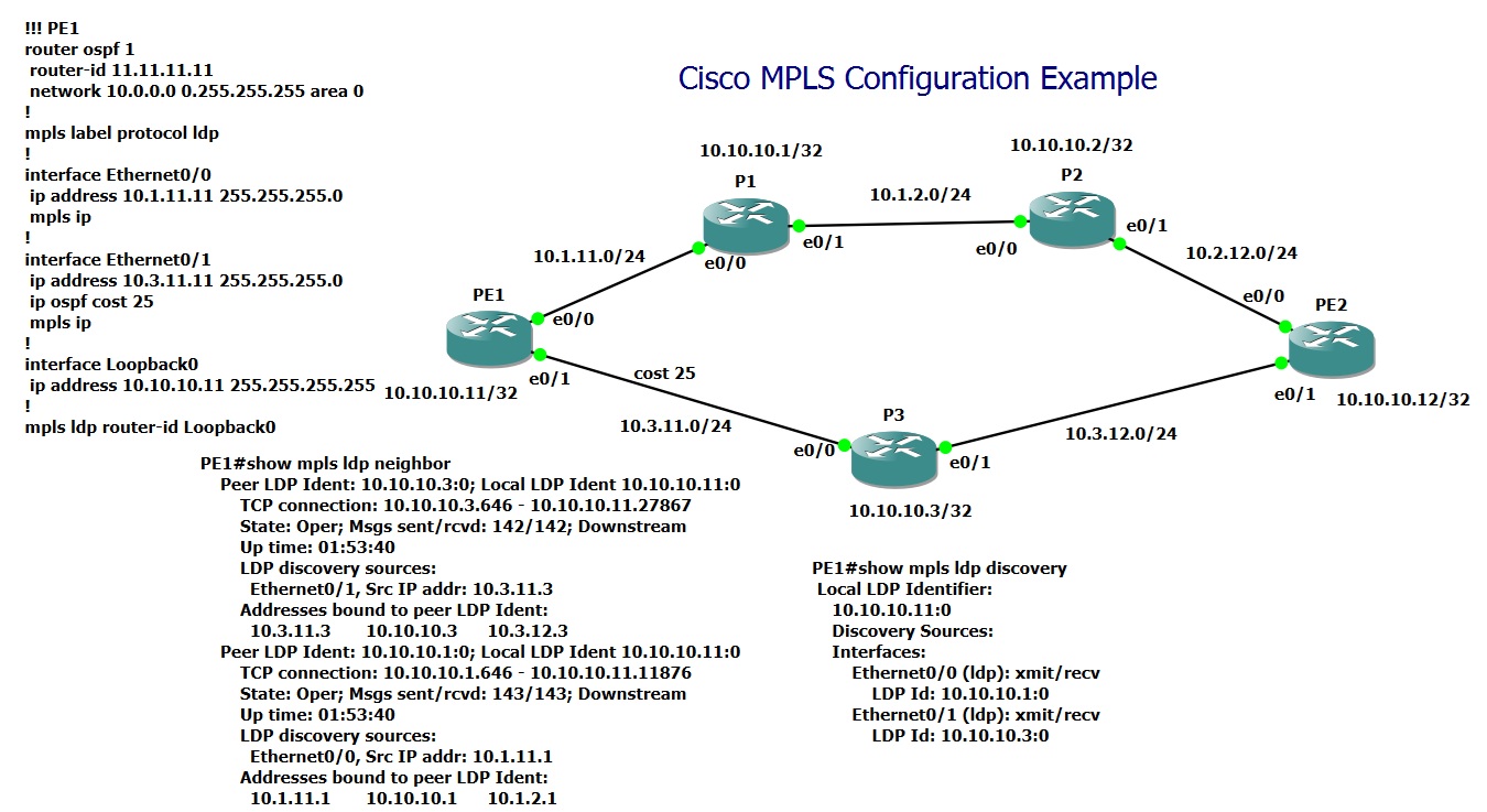
ip cef
!
mpls ip
mpls label protocol ldp
!
interface Ethernet0/0
 mpls ip
!
interface Loopback0
 ip address 10.10.10.11 255.255.255.255
!
mpls ldp router-id Loopback0
When you enable LDP on an interface, it periodically sends LDP Hello messages to the multicast address 224.0.0.2 (all routers) using UDP port 646 on that specific interface. This process is known as LDP Discovery.
Once neighbors are discovered, they establish a TCP connection on port 646 using their Router IDs. It is crucial that the Router IDs are reachable over TCP port 646, as this is required for successful LDP session establishment.
Using the command show mpls ldp discovery, you can view the results of the LDP discovery process which shows the Router ID of dicovered LDP neighbors.
PE1#show mpls ldp discovery
 Local LDP Identifier:
    10.10.10.11:0
    Discovery Sources:
    Interfaces:
        Ethernet0/0 (ldp): xmit/recv
            LDP Id: 10.10.10.1:0
        Ethernet0/1 (ldp): xmit/recv
            LDP Id: 10.10.10.3:0
To check the status of the established LDP sessions, use the command show mpls ldp neighbor. It is important that the state of each neighbor is shown as “Oper” when executing this command, indicating that the TCP session is established and operational.
PE1#show mpls ldp neighbor
    Peer LDP Ident: 10.10.10.3:0; Local LDP Ident 10.10.10.11:0
        TCP connection: 10.10.10.3.646 - 10.10.10.11.27867
        State: Oper; Msgs sent/rcvd: 125/125; Downstream
        Up time: 01:38:43
        LDP discovery sources:
          Ethernet0/1, Src IP addr: 10.3.11.3
        Addresses bound to peer LDP Ident:
          10.3.11.3       10.10.10.3      10.3.12.3
    Peer LDP Ident: 10.10.10.1:0; Local LDP Ident 10.10.10.11:0
        TCP connection: 10.10.10.1.646 - 10.10.10.11.11876
        State: Oper; Msgs sent/rcvd: 126/126; Downstream
        Up time: 01:38:43
        LDP discovery sources:
          Ethernet0/0, Src IP addr: 10.1.11.1
        Addresses bound to peer LDP Ident:
          10.1.11.1       10.10.10.1      10.1.2.1
LIB (Label Information Base)
As we discussed in the previous lesson, each router assigns a label to every subnet learned from the routing table and advertises these locally assigned labels to its LDP neighbors. Both locally assigned labels and labels received from neighbors for each subnet are stored in a table in the control plane called the LIB (Label Information Base).
You can view the contents of this table using the command show
mpls ldp binding on each router.
For example, this is the LIB table on router PE1, which shows the locally assigned labels and those received from neighboring routers (10.10.10.1 and 10.10.10.3) for each subnet.
PE1#show mpls ldp bindings
  lib entry: 10.1.2.0/24, rev 22
        local binding:  label: 24
        remote binding: lsr: 10.10.10.1:0, label: imp-null
        remote binding: lsr: 10.10.10.3:0, label: 24
  lib entry: 10.1.11.0/24, rev 5
        local binding:  label: imp-null
        remote binding: lsr: 10.10.10.3:0, label: 20
        remote binding: lsr: 10.10.10.1:0, label: imp-null
  lib entry: 10.2.12.0/24, rev 20
        local binding:  label: 23
        remote binding: lsr: 10.10.10.3:0, label: 21
        remote binding: lsr: 10.10.10.1:0, label: 21
  lib entry: 10.3.11.0/24, rev 6
        local binding:  label: imp-null
        remote binding: lsr: 10.10.10.3:0, label: imp-null
        remote binding: lsr: 10.10.10.1:0, label: 20
  lib entry: 10.3.12.0/24, rev 18
        local binding:  label: 22
        remote binding: lsr: 10.10.10.3:0, label: imp-null
        remote binding: lsr: 10.10.10.1:0, label: 24
  lib entry: 10.10.10.1/32, rev 16
        local binding:  label: 21
        remote binding: lsr: 10.10.10.1:0, label: imp-null
        remote binding: lsr: 10.10.10.3:0, label: 23
  lib entry: 10.10.10.2/32, rev 14
        local binding:  label: 20
        remote binding: lsr: 10.10.10.1:0, label: 19
        remote binding: lsr: 10.10.10.3:0, label: 22
  lib entry: 10.10.10.3/32, rev 12
        local binding:  label: 19
        remote binding: lsr: 10.10.10.3:0, label: imp-null
        remote binding: lsr: 10.10.10.1:0, label: 23
  lib entry: 10.10.10.11/32, rev 8
        local binding:  label: imp-null
        remote binding: lsr: 10.10.10.3:0, label: 19
        remote binding: lsr: 10.10.10.1:0, label: 18
  lib entry: 10.10.10.12/32, rev 10
        local binding:  label: 18
        remote binding: lsr: 10.10.10.3:0, label: 18
        remote binding: lsr: 10.10.10.1:0, label: 22
Take the subnet 10.10.10.2/32 as an example: router PE1 has assigned label 20, while its neighbors—P3 (10.10.10.3) and P1 (10.10.10.1)—have assigned labels 22 and 19, respectively.
As you can see, labels are locally significant, meaning that different routers can assign the same label to the same subnet.
Additionally, each router always assigns a specific label, “imp-null”, to its directly connected subnets for the purpose of PHP (Penultimate Hop Popping), as we discussed in the previous lesson.
For example, for the subnet 10.1.2.0/24, router P1 (10.10.10.1) assigns the label “imp-null” since it is directly connected to this subnet. Router P2 also assigns the “imp-null” label for the same subnet, but this label will not be visible on router PE1, as it only stores labels assigned by its neighboring routers.
Similarly, for the subnet 10.1.11.0/24, both PE1 and P1 assign the “imp-null” label, as this subnet is connected to both routers. However, router P3 assigns label 20 for this subnet.
FIB (Forwarding information base)
As you know, there are two tables in the data plane used for packet forwarding: the FIB (Forwarding Information Base) for forwarding incoming IP packets, and the LFIB (Label Forwarding Information Base) for forwarding incoming label-based packets.
The FIB in MPLS is essentially the same as the FIB used in an IP network, but with the addition of labels assigned by the next-hop router for each subnet.
To check the FIB table, we use the command show
ip cef.
For example, on router PE1, for the subnet 10.10.10.2, the next-hop IP address is 10.1.11.1 over interface Ethernet0/0. The label assigned by the next-hop router (19) is added as the outgoing label in the FIB table. This means that when an IP packet destined for 10.10.10.2 is received, it will be forwarded to 10.1.11.1 over interface Ethernet0/0 with the outgoing label “19“.
For the subnet 10.10.10.1, no outgoing label is assigned in the FIB table because the next-hop router assigns the “imp-null” label.
PE1#show ip cef 10.10.10.1
10.10.10.1/32
  nexthop 10.1.11.1 Ethernet0/0
PE1#show ip cef 10.10.10.2
10.10.10.2/32
  nexthop 10.1.11.1 Ethernet0/0 label 19
PE1#show mpls ldp bindings
...
  lib entry: 10.10.10.1/32, rev 16
        local binding:  label: 21
        remote binding: lsr: 10.10.10.1:0, label: imp-null
        remote binding: lsr: 10.10.10.3:0, label: 23
  lib entry: 10.10.10.2/32, rev 14
        local binding:  label: 20
        remote binding: lsr: 10.10.10.1:0, label: 19
        remote binding: lsr: 10.10.10.3:0, label: 22
...
LFIB (Label Forwarding information base)
Using the command show mpls forwarding-table, we can examine the LFIB (Label Forwarding Information Base) table.
For each subnet, there are two key labels:
Local Label – The label assigned by the router itself. If the router receives a packet with this label, it will process it based on the LFIB entry.
Outgoing Label – The label that replaces the local label before forwarding the packet to the next-hop router.
For example, for the subnet 10.10.10.2/32, the local label is “20”, and the outgoing label is “19”, which was assigned by the next-hop router. This means that if the router receives a packet with label “20”, it will swap it with “19” before forwarding it.
For the subnet 10.10.10.1/32, the local label is “21”, but the outgoing label is “imp-null”. This means that the router will pop the label instead of swapping it with another label, as part of the Penultimate Hop Popping (PHP) process.
PE1#show mpls forwarding-table
Local      Outgoing   Prefix           Bytes Label   Outgoing   Next Hop
Label      Label      or Tunnel Id     Switched      interface
18         22         10.10.10.12/32   0             Et0/0      10.1.11.1
19         Pop Label  10.10.10.3/32    0             Et0/1      10.3.11.3
20         19         10.10.10.2/32    0             Et0/0      10.1.11.1
21         Pop Label  10.10.10.1/32    0             Et0/0      10.1.11.1
22         Pop Label  10.3.12.0/24     0             Et0/1      10.3.11.3
23         21         10.2.12.0/24     0             Et0/0      10.1.11.1
24         Pop Label  10.1.2.0/24      0             Et0/0      10.1.11.1
PE1#show mpls ldp bindings
...
  lib entry: 10.10.10.1/32, rev 16
        local binding:  label: 21
        remote binding: lsr: 10.10.10.1:0, label: imp-null
        remote binding: lsr: 10.10.10.3:0, label: 23
  lib entry: 10.10.10.2/32, rev 14
        local binding:  label: 20
        remote binding: lsr: 10.10.10.1:0, label: 19
        remote binding: lsr: 10.10.10.3:0, label: 22
...
Tracing Packet Flow in the Data Plane
To better understand how packet forwarding works in the data plane, let’s walk through the process of forwarding an IP packet.
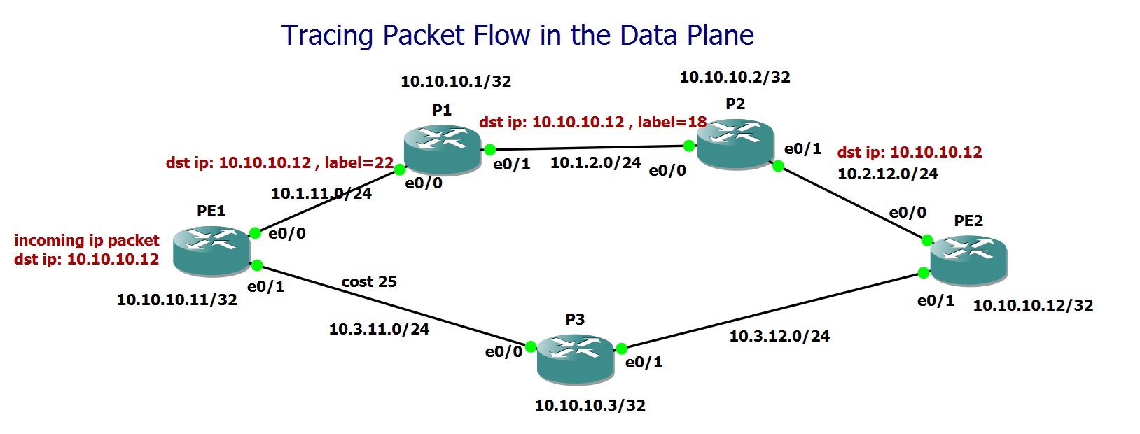
Suppose an IP packet is received by router PE1 with the destination address 10.10.10.12 (PE2 loopback interafce).
Router PE1 checks the FIB (Forwarding Information Base) table to forward the packet, since the incoming packet is an IP packet and not a labeled packet.
PE1#show ip cef 10.10.10.12/32
10.10.10.12/32
  nexthop 10.1.11.1 Ethernet0/0 label 22
FIB table for 10.10.10.12/32 shows that the packet should be forwarded to router P1 with IP address 10.1.11.1 over interface Ethernet0/0, and the outgoing label “22”, which is the label assigned by P1 for this subnet.
Router P1 receives the labeled packet, and since it’s a labeled packet, it checks the LFIB (Label Forwarding Information Base) to determine how to forward the packet.
P1#show mpls forwarding-table 10.10.10.12
Local      Outgoing   Prefix           Bytes Label   Outgoing   Next Hop
Label      Label      or Tunnel Id     Switched      interface
22         18         10.10.10.12/32   0             Et0/1      10.1.2.2
LFIB table for 10.10.10.12/32 in router P1 shows that the incoming label “22” (a local label) must be forwarded to the next-hop router P2 with IP address 10.1.2.2 over interface Ethernet0/1. The outgoing label is “18”, which is the local label assigned by P2 for this subnet.
In other words, each router in MPLS receives packets with a local label and forwards the packets with the next-hop label.
Router P2 receives the labeled packet with incoming label “18” (a local label). It checks the LFIB to forward the packet to the next-hop router.
P2#show mpls forwarding-table 10.10.10.12
Local      Outgoing   Prefix           Bytes Label   Outgoing   Next Hop
Label      Label      or Tunnel Id     Switched      interface
18         Pop Label  10.10.10.12/32   0             Et0/1      10.2.12.12
LFIB table for 10.10.10.12/32 in router P2 shows that the packet must be forwarded to PE2 with IP address 10.2.12.12 over interface Ethernet0/1, and the label needs to be popped before forwarding the packet to PE2. This is due to the Penultimate Hop Popping (PHP) rule, which we discussed in the previous lesson. The label will be popped in the router before reaching the last router for destinations directly connected to the last router.
Finally, router PE2 receives the IP packet since the label was popped by P2. It checks the FIB table to forward the packet and notices that the destination is locally connected to interface Loopback0.
PE2#show ip cef 10.10.10.12/32
10.10.10.12/32
  receive for Loopback0
FIB table for PE2 will show that the packet should be forwarded locally to Loopback0 for destination 10.10.10.12.
The output of the traceroute command in the MPLS network also confirms the same behavior for data plane packet forwarding, reflecting how labeled packets traverse the network.
PE1#traceroute 10.10.10.12 source 10.10.10.11
Type escape sequence to abort.
Tracing the route to 10.10.10.12
VRF info: (vrf in name/id, vrf out name/id)
  1 10.1.11.1 [MPLS: Label 22 Exp 0] 4 msec 1 msec 5 msec
  2 10.1.2.2 [MPLS: Label 18 Exp 0] 1 msec 1 msec 1 msec
  3 10.2.12.12 1 msec 2 msec 1 msec
PE1#
Understanding MPLS Label Structure
The final discussion in this section focuses on examining the structure of an MPLS label. To achieve this, I enabled MPLS packet capture on router P1’s Ethernet0/1 interface using the command debug mpls packet. Additionally, I used GNS3’s packet capture feature and analyzed the captured traffic in Wireshark.
Next, I sent a single ICMP packet from router PE1’s Loopback0 interface to router PE2’s Loopback interface. The Wireshark capture confirmed that an MPLS label consists of four main components.
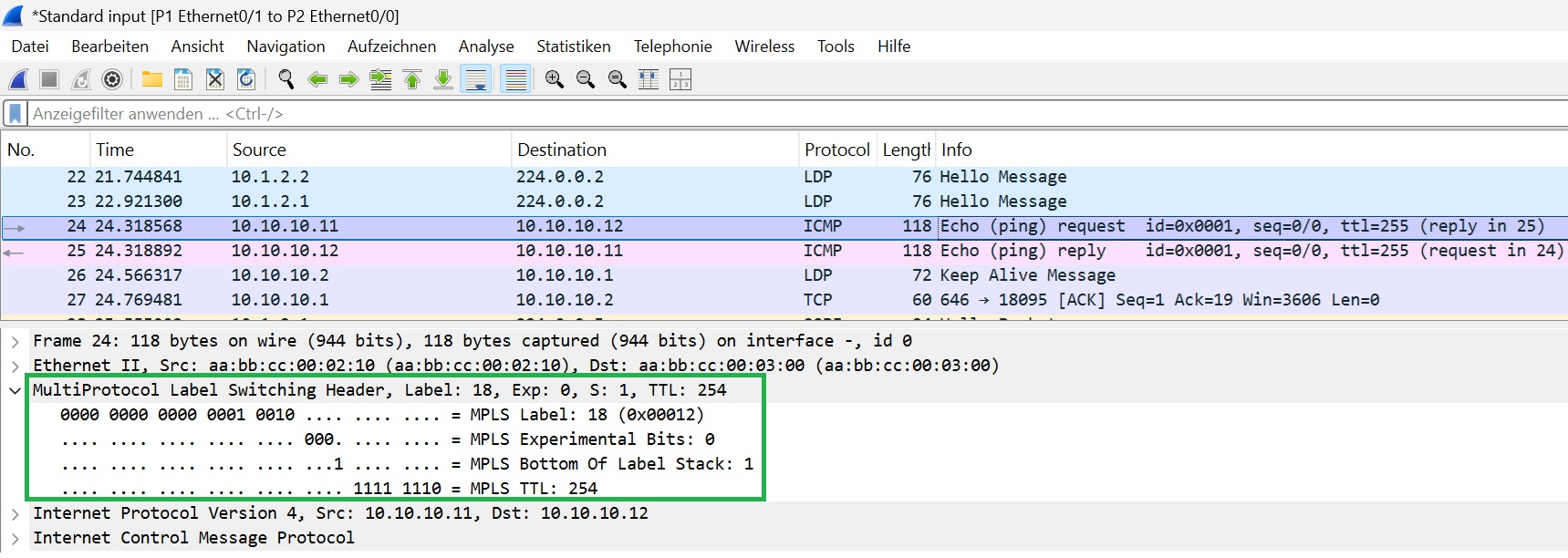
MPLS Label (20 bits)
This is the most crucial part of the MPLS header, as it determines how the packet is forwarded within the MPLS network. The label values we observe in the capture are exactly those we discussed throughout this course.
MPLS EXP (3 bits)
Also known as Experimental Bits, this field is used for Quality of Service (QoS) classification. It allows MPLS networks to differentiate traffic types and apply various service levels accordingly.
Bottom-of-Stack (S) Flag (1 bit)
This flag indicates whether the label is the last label in the stack.
If multiple labels are present (e.g., in MPLS VPN, which we will discuss later), this flag helps identify the final label in the stack.
S = 1 means this is the last label, while S = 0 means additional labels exist below it.
MPLS TTL (8 bits)
Similar to the Time-to-Live (TTL) field in IP headers, this field prevents routing loops in MPLS networks. The TTL value decreases with each hop, and if it reaches zero, the packet is discarded.
The output of the debug mpls packet command on router P1 provides the same MPLS label information as the Wireshark capture. However, it does not explicitly display the Bottom-of-Stack (S) bit, which indicates whether a label is the last one in the stack.
PE1#ping 10.10.10.12 source 10.10.10.11 repeat 1
Type escape sequence to abort.
Sending 1, 100-byte ICMP Echos to 10.10.10.12, timeout is 2 seconds:
Packet sent with a source address of 10.10.10.11
!
Success rate is 100 percent (1/1), round-trip min/avg/max = 5/5/5 ms
P1#debug mpls packet ethernet 0/1
Packet debugging is on on idb Ethernet0/1
P1#
*Mar 12 21:16:33.029: MPLS les: Et0/1: rx: Len 118 Stack {18 0 254} - ipv4 data s:10.10.10.12 d:10.10.10.11 ttl:255 tos:0 prot:1
P1#