In MPLS VPNs where OSPF is used between the PE and CE routers, the Domain-ID helps the PE routers know if a route comes from the same OSPF site or a different one. When a PE sends an OSPF route into BGP, it includes the Domain-ID. If another PE receives the route and the Domain-ID matches its own, it keeps the original OSPF route type (like intra-area or inter-area). But if the Domain-ID is different, the PE treats the route as external (Type 5) to avoid routing problems or loops.
OSPF PE-CE routing within an MPLS VPN infrastructure allows customers to run OSPF between their remote sites without requiring direct leased lines. This is made possible through the concept of the OSPF Superbackbone, which extends OSPF connectivity across the MPLS core. In this lesson, we will explain how this mechanism works. In the next lesson, we will demonstrate how to configure the OSPF Superbackbone in an MPLS VPN environment.
OSPF PE-CE Routing Fundamental in MPLS VPN
As you may know, in OSPF routing, all non-backbone areas must connect to Area 0 to ensure proper route propagation. However, when customer sites are connected through an MPLS backbone, there’s no direct connectivity—such as a leased line—between these sites, and the MPLS core is managed by the service provider, not the customer.
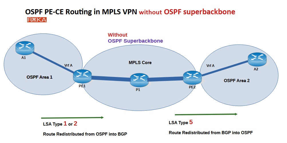
When OSPF is configured between the Provider Edge (PE) and Customer Edge (CE) routers, OSPF routes typically need to be redistributed into BGP within the MPLS VPN infrastructure. These routes are then redistributed back from BGP into OSPF on the remote PE routers to reach other customer sites.
This process causes OSPF routes to be converted into Type 5 External LSAs (LSA Type 5), which have lower priority in OSPF’s route selection and are flooded throughout the entire OSPF domain. This behavior is inconsistent with standard OSPF operation and usually not desired by customers.
OSPF Superbackbone Concept
The OSPF Superbackbone concept resolves the limitations of running OSPF across an MPLS VPN infrastructure. In a typical OSPF design, all areas must connect to Area 0 (the backbone area). However, when customer sites are connected over an MPLS backbone—which is outside the customer’s control and lacks direct links between sites (e.g., no leased lines)—this design constraint poses a challenge.
With the OSPF Superbackbone, non-backbone areas such as Area 1 and Area 2 are connected through MPLS VPN core, which acts as a logical Area 0.
The Provider Edge (PE) routers—PE1 and PE2—connect the customer’s OSPF domains to the MPLS backbone. From the customer’s perspective, these PE routers act as OSPF Area Border Routers (ABRs), maintaining the integrity of the OSPF area structure.
How Does the OSPF Superbackbone Work?
The OSPF Superbackbone preserves original OSPF route attributes—including LSA type, area number, OSPF router ID, and OSPF domain ID—by transporting this information across the MPLS core using BGP extended communities. On the receiving end, the remote PE router uses this metadata to reconstruct the LSAs, making it appear as if the sites are directly connected through a common Area 0.
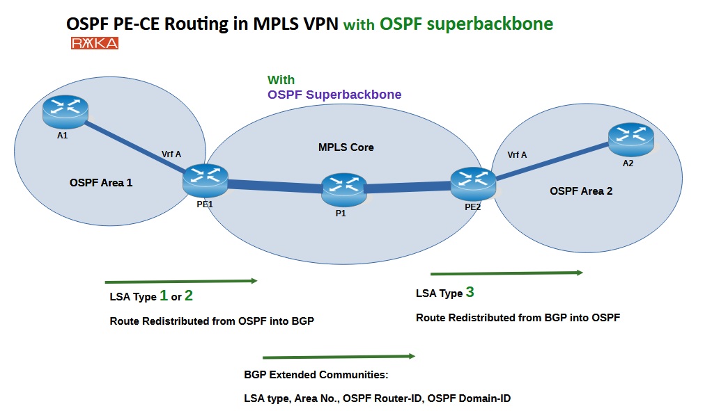
This approach maintains the OSPF hierarchy and behavior as expected, avoiding the need for route redistribution (which would normally convert intra-area or inter-area LSAs into external LSAs) and ensuring optimal route selection and loop-free routing.
OSPF Superbackbone operates by default when OSPF is enabled across the MPLS core in an MPLS VPN environment; it does not require any special configuration.
BGP Extended Communities for OSPF PE-CE Routing Example1:
This image is a CLI output from a PE router (PE2) showing a BGP VPNv4 route that carries OSPF route information across an MPLS VPN. This output is an example of how the OSPF Superbackbone concept works in practice.
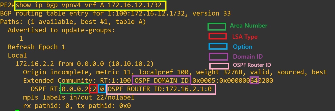
LSA Type is 2 🔴, indicating it’s an intra-area route. The Area Number is 0.0.0.2 🟩, showing where the route originated. The Option field is 0x64 🔵, which includes flags for external routes; the value “1” signifies an E2 route. The OSPF Domain ID is also 0x64 (100) 🟣, which i explain shortly. by default matching the OSPF Process-ID unless manually set. Finally, the Router ID is 172.16.2.1 🩷, identifying the originating PE router (PE1).
| Field | Value | Meaning | Highlight Color |
|---|---|---|---|
| OSPF LSA Type | 2 | This is an intra-area route (LSA Type 2) | 🔴 Red |
| OSPF Area Number | 0.0.0.2 | The area the route originated from | 🟩 Green |
| Option | 0x64 | Used for external routes. when “1” means E2 | 🔵 Blue |
| OSPF Domain ID | 0x64=100 | By default equal to OSPF Process-ID. | 🟣 Purple |
| OSPF Router ID | 172.16.2.1 | The originating OSPF router ID (PE1) | 🩷 Pink |
OSPF PE-CE Routing – Domain-ID (Example 2)
You can change the Domain-ID when you want to separate two OSPF sites so they treat each other’s routes as external, even if they are in the same VPN. Or you can keep the same Domain-ID if you want to connect two sites and preserve OSPF route types between them.
By default, the Domain-ID is set to the OSPF process ID. It can be explicitly configured using the command:
router ospf 100 vrf A
 domain-id 0.0.0.1
In this example, BGP VPNv4 route on PE2 for prefix 172.16.13.1/32 was redistributed into BGP by PE3 in VRF B. Before changing PE3’s Domain-ID, both PE2 and PE3 shared the same OSPF Domain-ID, so PE2 recognized the route as originating from the same OSPF domain. This allowed PE2 to preserve the original OSPF route type (such as inter-area Type 3) when redistributing it to its connected CE router.
PE2#show ip bgp vpnv4 vrf B 172.16.13.1/32
BGP routing table entry for 1:200:172.16.13.1/32, version 25
Paths: (1 available, best #1, table B)
  Not advertised to any peer
  Refresh Epoch 1
  Local
    10.10.10.3 (metric 21) from 10.10.10.3 (10.10.10.3)
      Origin incomplete, metric 11, localpref 100, valid, internal, best
      Extended Community: RT:1:200 OSPF DOMAIN ID:0x0005:0x000000C80200
        OSPF RT:0.0.0.1:2:0 OSPF ROUTER ID:172.16.3.1:0
      mpls labels in/out nolabel/24
      rx pathid: 0, tx pathid: 0x0
After PE3’s Domain-ID was changed to 3.3.3.3, the Domain-ID in the BGP route no longer matched PE2’s. Consequently, PE2 treated the route as coming from a different OSPF domain and converted it into an external route (Type 5 with E2 metric) when redistributing it into OSPF. This mechanism helps prevent routing loops between distinct OSPF domains.
PE3(config)#router ospf 200 vrf B
PE3(config-router)#domain-id 3.3.3.3
PE3(config-router)#
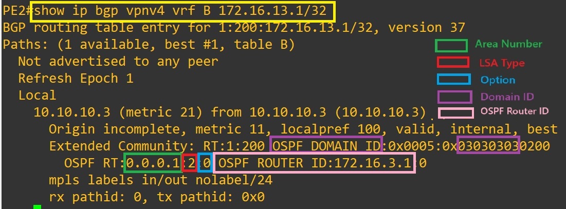
PE2#show ip bgp vpnv4 vrf B 172.16.13.1/32
BGP routing table entry for 1:200:172.16.13.1/32, version 37
Paths: (1 available, best #1, table B)
  Not advertised to any peer
  Refresh Epoch 1
  Local
    10.10.10.3 (metric 21) from 10.10.10.3 (10.10.10.3)
      Origin incomplete, metric 11, localpref 100, valid, internal, best
      Extended Community: RT:1:200 OSPF DOMAIN ID:0x0005:0x030303030200
        OSPF RT:0.0.0.1:2:0 OSPF ROUTER ID:172.16.3.1:0
      mpls labels in/out nolabel/24
      rx pathid: 0, tx pathid: 0x0
B2#show ip route ospf
...

Gateway of last resort is not set

      172.16.0.0/16 is variably subnetted, 6 subnets, 2 masks
O E2     172.16.3.0/24 [110/1] via 172.16.4.1, 00:00:30, Ethernet0/0
O E2     172.16.13.1/32 [110/11] via 172.16.4.1, 00:00:30, Ethernet0/0
B2#
| Step | Domain-ID Seen by PE2 | Domain Match? | Redistributed as |
|---|---|---|---|
| Before change | 0.0.0.200 | ✅ Yes | Original OSPF Type (e.g., Type 3) |
| After change | 3.3.3.3 | ❌ No | External (Type 5, E2) |