MPLS VPN Extranet Topology allows multiple organizations (usually separate VPNs) to securely share specific resources or services over a common MPLS backbone, without exposing their entire network. In this lesson, we’ll discuss and demonstrate how this topology works in practice.
Extranet Topology in MPLS VPN
Extranet VPN Topology allows controlled communication between different MPLS VPNs—commonly for B2B integration—while keeping internal networks isolated.
In this example, customers A and B each have two sites with full internal connectivity. Their central offices also need shared service access.
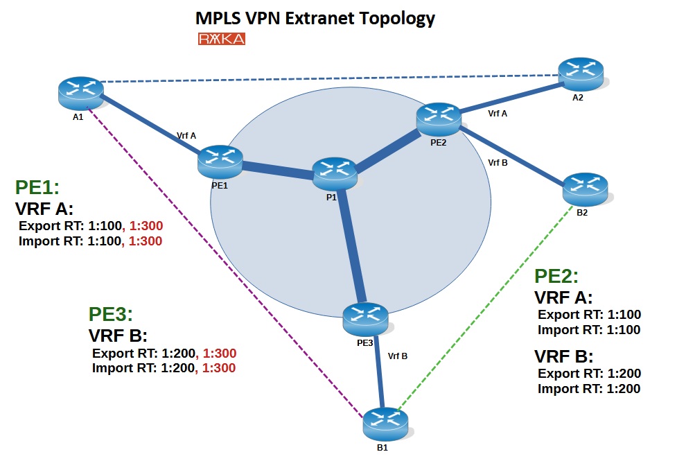
Route Targets:
Customer A: 1:100 (export/import)
Customer B: 1:200 (export/import)
Shared Services (central sites only): 1:300 (export/import)
This setup ensures that each customer’s internal traffic remains isolated, while only the central offices can exchange routes and access shared services—providing secure, selective connectivity.
Extranet Topology Configuration Example
This is a sample MPLS VPN Extranet topology implemented in GNS3. Within the provider network, OSPF and MPLS are configured, and two VRFs—VRF A and VRF B—are defined. Interfaces connecting to customer sites are assigned to the appropriate VRFs. MP-BGP with the VPNv4 address family is established between PE routers, and routes from each VRF are redistributed into MP-BGP for propagation across the MPLS core.
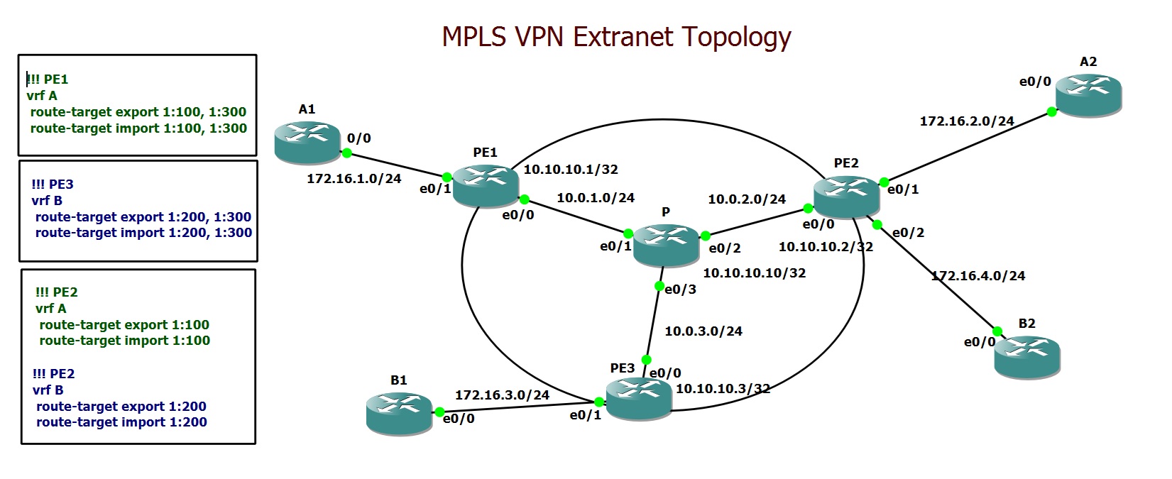
Route-targets are configured as follows: RT 1:100 for VRF A and RT 1:200 for VRF B (both for import and export), and RT 1:400 is used on the central sites of both VRFs to enable controlled sharing of services between these two customers.
Troubleshooting Extranet Topology
To verify that the Extranet topology is functioning correctly, I begin by checking connectivity from the customer sites. From A1 (Customer A’s central site), I can successfully reach A2 (Customer A’s branch) and B1 (Customer B’s central site), as expected. Similarly, from B1, there is connectivity to B2 and to A1.
However, branch sites should not be able to reach the central site of the other customer. In other words, A2 must not have connectivity to B1, and B2 must not be able to reach A1. This confirms that only the designated central sites can communicate, while branch-to-branch or branch-to-foreign-central-site access is blocked.
A1#traceroute 172.16.2.2
Type escape sequence to abort.
Tracing the route to 172.16.2.2
VRF info: (vrf in name/id, vrf out name/id)
  1 172.16.1.1 5 msec 5 msec 5 msec
  2 10.0.1.10 [MPLS: Labels 21/22 Exp 0] 4 msec 5 msec 4 msec
  3 172.16.2.1 4 msec 6 msec 3 msec
  4 172.16.2.2 5 msec 0 msec 2 msec
!
A1#traceroute 172.16.3.2
Type escape sequence to abort.
Tracing the route to 172.16.3.2
VRF info: (vrf in name/id, vrf out name/id)
  1 172.16.1.1 1 msec 6 msec 5 msec
  2 10.0.1.10 [MPLS: Labels 19/22 Exp 0] 2 msec 0 msec 1 msec
  3 172.16.3.1 1 msec 0 msec 1 msec
  4 172.16.3.2 0 msec 0 msec 0 msec
A1#
B1#traceroute 172.16.4.2
Type escape sequence to abort.
Tracing the route to 172.16.4.2
VRF info: (vrf in name/id, vrf out name/id)
  1 172.16.3.1 5 msec 5 msec 5 msec
  2 10.0.3.10 [MPLS: Labels 21/23 Exp 0] 1 msec 1 msec 1 msec
  3 172.16.4.1 0 msec 5 msec 5 msec
  4 172.16.4.2 1 msec 0 msec 0 msec
!
B1#traceroute 172.16.1.2
Type escape sequence to abort.
Tracing the route to 172.16.1.2
VRF info: (vrf in name/id, vrf out name/id)
  1 172.16.3.1 6 msec 5 msec 5 msec
  2 10.0.3.10 [MPLS: Labels 20/22 Exp 0] 5 msec 4 msec 5 msec
  3 172.16.1.1 5 msec 6 msec 1 msec
  4 172.16.1.2 0 msec 1 msec 1 msec
B1#
A2#traceroute 172.16.3.2
Type escape sequence to abort.
Tracing the route to 172.16.3.2
VRF info: (vrf in name/id, vrf out name/id)
  1 172.16.2.1 2 msec 6 msec 6 msec
  2 172.16.2.1 !H  !H  !H
By examining the BGP table for each VRF, we can further confirm the correct operation of the Extranet topology. For instance, on PE1 in VRF A, the BGP table includes a route to Customer B’s central office subnet (172.16.3.0/24). Similarly, on PE3 in VRF B, we see a route to Customer A’s central office subnet (172.16.1.0/24). This indicates that central sites have the necessary routes to communicate with each other.
However, this is not the case for the PE routers connected to the branch sites. On PE2, both VRF A and VRF B BGP tables contain only the internal routes of their respective customers. There are no routes to the central site of the other customer, confirming that branch sites cannot reach external networks outside their own VPN.
PE1#show ip bgp vpnv4 all
BGP table version is 11, local router ID is 10.10.10.1
Status codes: s suppressed, d damped, h history, * valid, > best, i - internal,
              r RIB-failure, S Stale, m multipath, b backup-path, f RT-Filter,
              x best-external, a additional-path, c RIB-compressed,
Origin codes: i - IGP, e - EGP, ? - incomplete
RPKI validation codes: V valid, I invalid, N Not found

     Network          Next Hop            Metric LocPrf Weight Path
Route Distinguisher: 1:100 (default for vrf A)
 *>  172.16.1.0/24    0.0.0.0                  0         32768 ?
 *>i 172.16.2.0/24    10.10.10.2               0    100      0 ?
 *>i 172.16.3.0/24    10.10.10.3               0    100      0 ?
Route Distinguisher: 1:200
 *>i 172.16.3.0/24    10.10.10.3               0    100      0 ?
PE1#
!
PE1#show ip bgp vpnv4 all labels
   Network          Next Hop      In label/Out label
Route Distinguisher: 1:100 (A)
   172.16.1.0/24    0.0.0.0         22/nolabel(A)
   172.16.2.0/24    10.10.10.2      nolabel/22
   172.16.3.0/24    10.10.10.3      nolabel/22
Route Distinguisher: 1:200
   172.16.3.0/24    10.10.10.3      nolabel/22

PE1#
PE3#show ip bgp vpnv4 all
BGP table version is 11, local router ID is 10.10.10.3
Status codes: s suppressed, d damped, h history, * valid, > best, i - internal,
              r RIB-failure, S Stale, m multipath, b backup-path, f RT-Filter,
              x best-external, a additional-path, c RIB-compressed,
Origin codes: i - IGP, e - EGP, ? - incomplete
RPKI validation codes: V valid, I invalid, N Not found

     Network          Next Hop            Metric LocPrf Weight Path
Route Distinguisher: 1:100
 *>i 172.16.1.0/24    10.10.10.1               0    100      0 ?
Route Distinguisher: 1:200 (default for vrf B)
 *>i 172.16.1.0/24    10.10.10.1               0    100      0 ?
 *>  172.16.3.0/24    0.0.0.0                  0         32768 ?
 *>i 172.16.4.0/24    10.10.10.2               0    100      0 ?
PE3#

!
PE3#show ip bgp vpnv4 all labels
   Network          Next Hop      In label/Out label
Route Distinguisher: 1:100
   172.16.1.0/24    10.10.10.1      nolabel/22
Route Distinguisher: 1:200 (B)
   172.16.1.0/24    10.10.10.1      nolabel/22
   172.16.3.0/24    0.0.0.0         22/nolabel(B)
   172.16.4.0/24    10.10.10.2      nolabel/23

PE3#
PE2#show ip bgp vpnv4 all
BGP table version is 15, local router ID is 10.10.10.2
Status codes: s suppressed, d damped, h history, * valid, > best, i - internal,
              r RIB-failure, S Stale, m multipath, b backup-path, f RT-Filter,
              x best-external, a additional-path, c RIB-compressed,
Origin codes: i - IGP, e - EGP, ? - incomplete
RPKI validation codes: V valid, I invalid, N Not found

     Network          Next Hop            Metric LocPrf Weight Path
Route Distinguisher: 1:100 (default for vrf A)
 *>i 172.16.1.0/24    10.10.10.1               0    100      0 ?
 *>  172.16.2.0/24    0.0.0.0                  0         32768 ?
Route Distinguisher: 1:200 (default for vrf B)
 *>i 172.16.3.0/24    10.10.10.3               0    100      0 ?
 *>  172.16.4.0/24    0.0.0.0                  0         32768 ?
PE2#
Extranet Topology Full Concfiguration
Below is the complete configuration of the PE routers for the Extranet VPN topology.
## PE1
hostname PE1
!
ip vrf A
 rd 1:100
 route-target export 1:100
 route-target export 1:300
 route-target import 1:100
 route-target import 1:300
!
ip cef
!
mpls label protocol ldp
!
interface Loopback0
 ip address 10.10.10.1 255.255.255.255
!
interface Ethernet0/0
 ip address 10.0.1.1 255.255.255.0
 mpls ip
!
interface Ethernet0/1
 ip vrf forwarding A
 ip address 172.16.1.1 255.255.255.0
!
router ospf 1
 network 10.0.0.0 0.255.255.255 area 0
!
router bgp 65001
 bgp log-neighbor-changes
 neighbor 10.10.10.2 remote-as 65001
 neighbor 10.10.10.2 update-source Loopback0
 neighbor 10.10.10.3 remote-as 65001
 neighbor 10.10.10.3 update-source Loopback0
 !
 address-family vpnv4
  neighbor 10.10.10.2 activate
  neighbor 10.10.10.2 send-community both
  neighbor 10.10.10.2 next-hop-self
  neighbor 10.10.10.3 activate
  neighbor 10.10.10.3 send-community both
  neighbor 10.10.10.3 next-hop-self
 exit-address-family
 !
 address-family ipv4 vrf A
  redistribute connected
 exit-address-family
!
mpls ldp router-id Loopback0
## PE2
hostname PE2
!
ip vrf A
 rd 1:100
 route-target export 1:100
 route-target import 1:100
!
ip vrf B
 rd 1:200
 route-target export 1:200
 route-target import 1:200
!
ip cef
!
mpls label protocol ldp
!
interface Loopback0
 ip address 10.10.10.2 255.255.255.255
!
interface Ethernet0/0
 ip address 10.0.2.2 255.255.255.0
 mpls ip
!
interface Ethernet0/1
 ip vrf forwarding A
 ip address 172.16.2.1 255.255.255.0
!
interface Ethernet0/2
 ip vrf forwarding B
 ip address 172.16.4.1 255.255.255.0
!
router ospf 1
 network 10.0.0.0 0.255.255.255 area 0
!
router bgp 65001
 bgp log-neighbor-changes
 neighbor 10.10.10.1 remote-as 65001
 neighbor 10.10.10.1 update-source Loopback0
 neighbor 10.10.10.3 remote-as 65001
 neighbor 10.10.10.3 update-source Loopback0
 !
 address-family vpnv4
  neighbor 10.10.10.1 activate
  neighbor 10.10.10.1 send-community both
  neighbor 10.10.10.1 next-hop-self
  neighbor 10.10.10.3 activate
  neighbor 10.10.10.3 send-community both
  neighbor 10.10.10.3 next-hop-self
 exit-address-family
 !
 address-family ipv4 vrf A
  redistribute connected
 exit-address-family
 !
 address-family ipv4 vrf B
  redistribute connected
 exit-address-family
!
mpls ldp router-id Loopback0
## PE3
hostname PE3
!
ip vrf B
 rd 1:200
 route-target export 1:200
 route-target export 1:300
 route-target import 1:200
 route-target import 1:300
!
ip cef
!
mpls label protocol ldp
!
interface Loopback0
 ip address 10.10.10.3 255.255.255.255
!
interface Ethernet0/0
 ip address 10.0.3.3 255.255.255.0
 mpls ip
!
interface Ethernet0/1
 ip vrf forwarding B
 ip address 172.16.3.1 255.255.255.0
!
router ospf 1
 network 10.0.0.0 0.255.255.255 area 0
!
router bgp 65001
 bgp log-neighbor-changes
 neighbor 10.10.10.1 remote-as 65001
 neighbor 10.10.10.1 update-source Loopback0
 neighbor 10.10.10.2 remote-as 65001
 neighbor 10.10.10.2 update-source Loopback0
 !
 address-family vpnv4
  neighbor 10.10.10.1 activate
  neighbor 10.10.10.1 send-community both
  neighbor 10.10.10.1 next-hop-self
  neighbor 10.10.10.2 activate
  neighbor 10.10.10.2 send-community both
  neighbor 10.10.10.2 next-hop-self
 exit-address-family
 !
 address-family ipv4 vrf B
  redistribute connected
 exit-address-family
!
mpls ldp router-id Loopback0