Table of Contents
F5 Active-Active HA configuration provides the capability to use different BIG-IP for different applications so that all F5 devices process and forward traffic simultaneously.
In this section we will configure F5 Active-Active HA. However, make sure you already know the details of the Active-Standby HA configuration that we discussed in the previous sections.
F5 BIG-IP Active-Active HA Fundamental
This is the topology we already used to implement Active-Standby HA. There are some changes that make them ready to implement Active-Active HA.
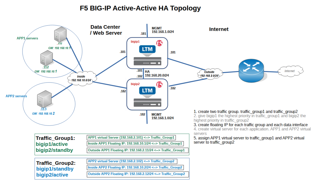
Two BIG-IP devices named “bigip1” and “bigip2” are connected to four networks, internal with the subnet 192.168.10.0/24, external with the subnet 192.168.2.0/24, management with the subnet 192.168.1.0/ 24 and finally HA with the subnet 192.168.20.0/24.
The IP address of “bigip1” is “.181” and the IP address of “bigip2” is “.182” on all of these networks.
To implement active-active HA configuration, we need at least two applications.
In the first application, bigip1 is the active device and bigip2 is the standby device and in the second application, vice versa, bigip2 is the active device and bigip1 is the standby device.
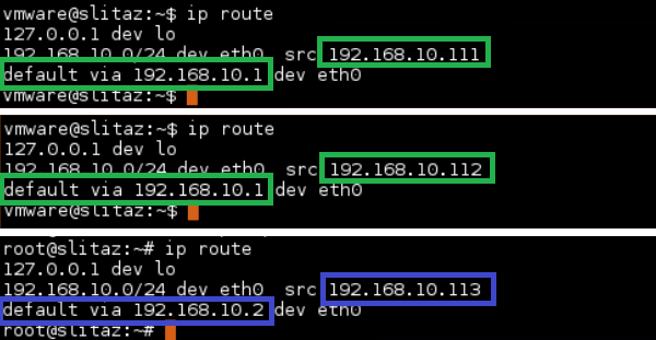
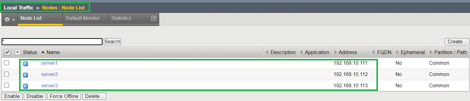
Here I am using servers with IP address 192.168.10.111 and 192.168.10.112 as first application with HTTP service and server with IP address 192.168.10.113 for second application with SSH service.
Note that the gateway of the servers with the first application is 192.168.10.1, but the gateway of the server with the second application is 192.168.10.2. I will explain the reason behind that shortly.
In the real scenario, it is also possible to locate different applications in different subnets, with each gateway located in its own corresponding subnet.
Active-Active configuration also requires that you configure at least two traffic groups. In traffic group1 created in the previous sections, bigip1 is the active device and bigip2 is the standby device. For traffic group2, which needs to be added in this section, it is the other way around.
We also need to configure two different virtual servers in BIG-IP devices, one for the first application and one for the second application.
It is important to assign the first virtual server to one traffic group and the second virtual server to the other traffic group.
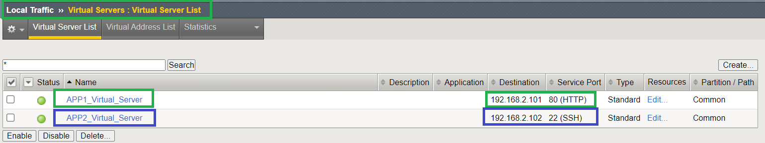
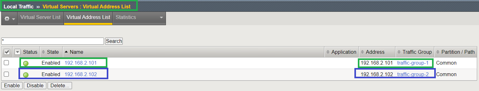
We will create the APP1 virtual server with virtual IP 192.168.2.101 and APP2 virtual server with virtual IP 192.168.2.102. APP1 virtual server is assigned to traffic group1 and APP2 virtual server is assigned to the traffic group2.
For each traffic group, we also need a dedicated floating IP on each data interface that will be used to route traffic through the active BIG-IP device.
The IP addresses 192.168.10.1 and 192.168.2.11 will be configured in traffic group1 on internal and external networks.
In traffic group2, the IP addresses 192.168.10.2 and 192.168.2.12 are configured for internal and external networks.
For this reason, the gateway of the servers belonging to traffic group1 is configured to 192.168.10.1, and 192.168.10.2 is configured for the gateway of the servers in traffic group2.
create traffic groups
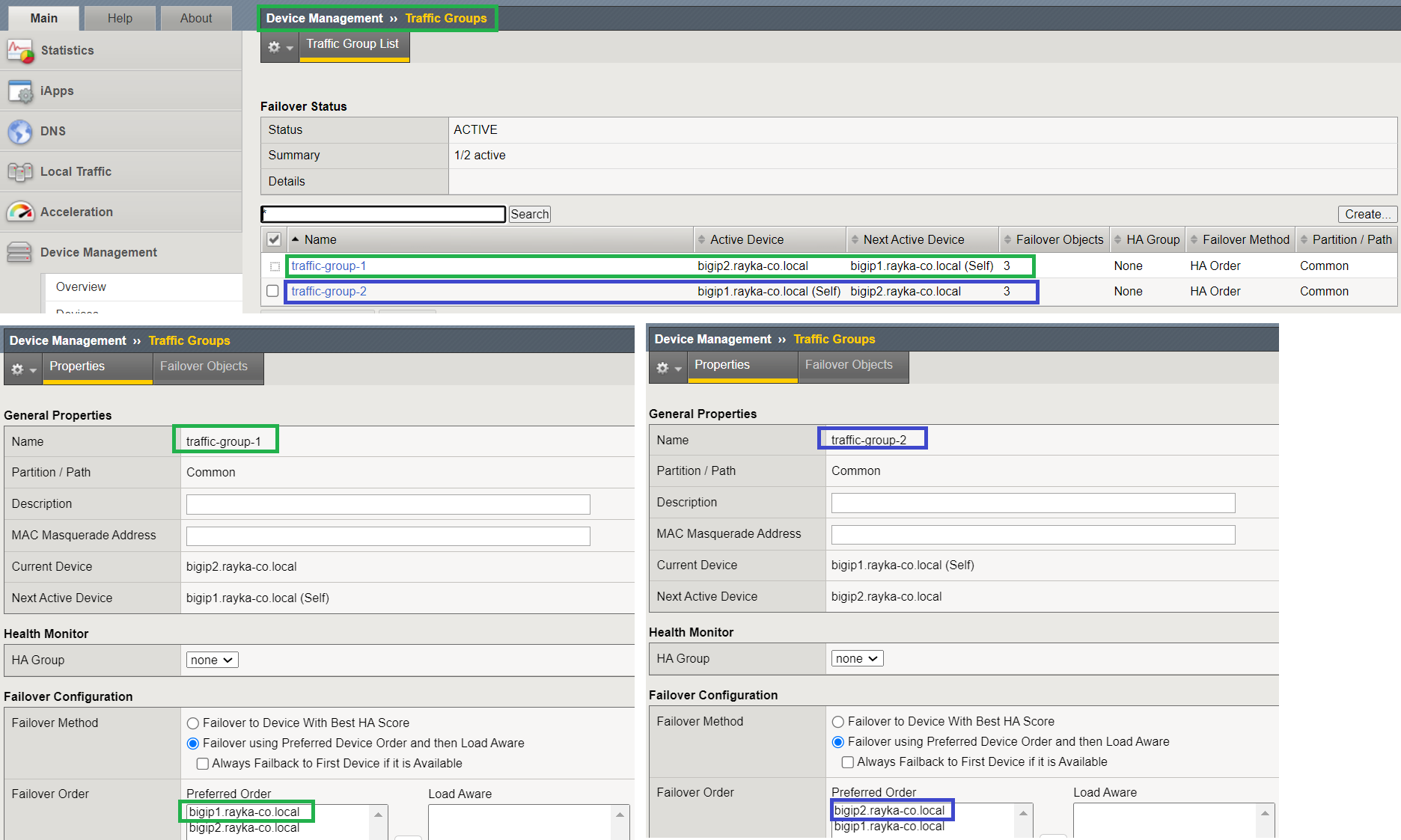
to start implementing active active HA configuration, In the first step we have to configure two traffic groups.
The first traffic group is automatically created in the active-standby HA configuration.
In the first traffic group, we give bigip1 as the first priority and bigip2 as the second priority.
Then we create a second traffic group, but with bigip2 as the first priority and bigip1 as the second priority.
create floating IP
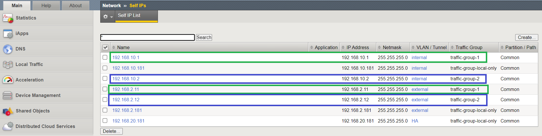
Then for each traffic group and data interface, we create a dedicated floating IP which will be used to route traffic through active BIG-IP.
According to the design, IP addresses 192.168.10.1 and 192.168.2.11 are assigned to traffic group1 and IP addresses 192.168.10.2 and 192.168.2.12 are assigned to traffic group2.
set gateway of servers to floating IP
We must not forget to configure the gateway IP address of the servers behind BIG-IP to the corresponding floating IP address.
I have already configured the gateway IP address of Server1 and Server2 belonging to the first application to 192.168.10.1 and the gateway IP address of Server3 belonging to the second application to 192.168.10.2 which are floating IP address of internal interface in traffic group1 and traffic group2.
create application virtual services
To create application services on F5 BIG-IP, we first create server nodes including all three servers.
Then we create two pools, one for the HTTP service including the first two servers and one for the SSH service including the third server.

And finally, we create two virtual application servers, one with IP address 192.168.2.101 including HTTP pool and the other with IP address 192.168.2.102 including SSH pool.
assign each virtual server to the appropriate traffic group
To ensure that traffic from one application goes through the first BIG-IP device and traffic from the second application goes through the second BIG-IP, we assign virtual server APP1 to traffic group1 and virtual server APP2 to traffic group2.
TEST and Monitor F5 active-active HA
Now F5 active-active HA configuration is completed and ready to be tested.
I want to make sure that traffic to the first application goes over a BIG-IP and traffic to the second application goes over other BIG-IP.
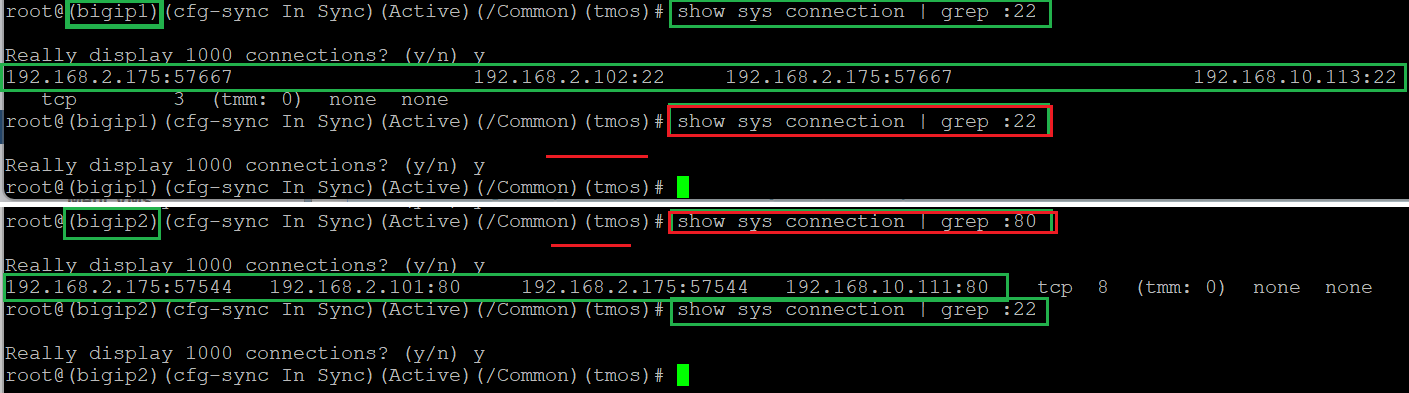
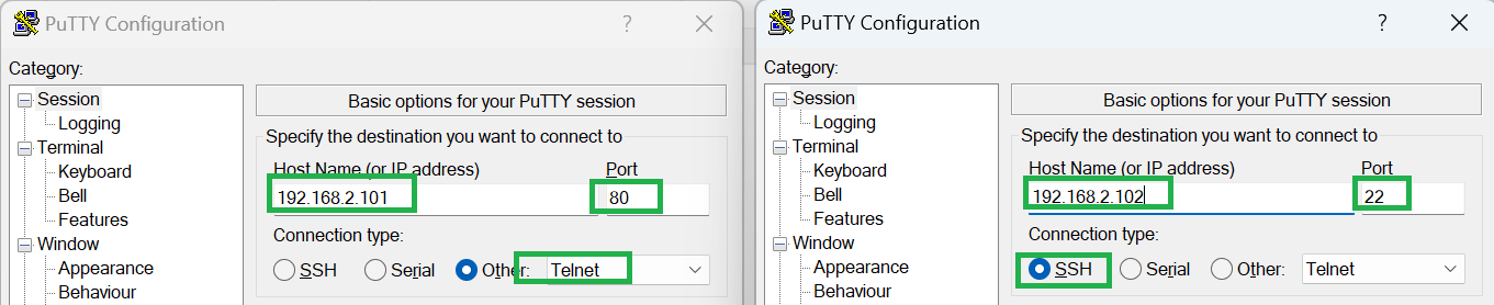
We create two connections with two applications. One to the IP address 192.168.2.101 and port 80 and the second to the IP address 192.168.2.102 and the SSH port.
Now we check the active connections in the BIG-IP devices to ensure that they are working properly as expected.