Cisco SD-WAN subinterface configuration is the subject of this section to overcome the limitations of the physical interface in WAN edge routers.
Creating sub-interfaces is generally not an important concept to talk about. However, there are two small points in creating a subinterface in a Cisco SD-WAN environment. That is why I decided to create this video.
Cisco SD-WAN Subinterface Overview
It is usually necessary to create sub-interfaces in routers because they have more limitation on the number of physical interfaces comparing to switches.
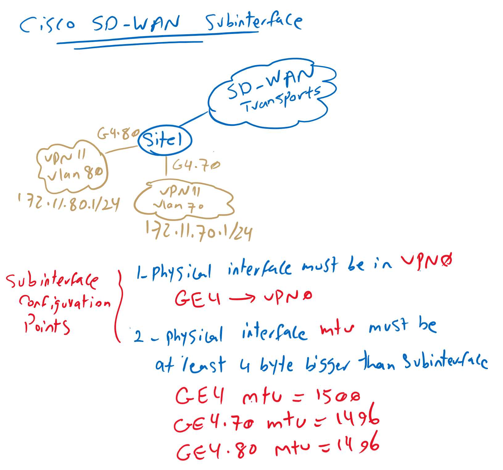
In our topology, I will create two subinterface in GigabitEthernet4 in VPN11. GigabitEthernet4.70 in VLAN 70 with IP subnet 172.11.70.0/24 and GigabitEthernet4.80 in VLAN 80 with IP subnet 172.11.80.0/24.
There are two points to create subinterface in Cisco SD-WAN infrastructure. the first is that parent physical interface in which subinterface will be created must be in VPN0 . in our example, GigabitEthernet4 must be in VPN0.
and the second point is that MTU of physical interface must be at least 4 Byte bigger than MTU of subinterface. For example if MTU of physical interface is 1500 by default then we configure MTU of subinterfaces to 1496.
Cisco SD-WAN Subinterface Configuration
We start our configuration by configuring our physical interface GigabitEthernet4 into VPN0.
First we create a new feature template for activating GigabitEthernet4. Then we put in into VPN0.
CONFIGURATION -> TEMPLATES -> Feature -> Add Template -> Device: CSR1000v -> Cisco VPN Interface Ethernet
 Template Name: CSR1000v_VPN0_GigabitEthernet4
 Description: CSR1000v_VPN0_GigabitEthernet4
  Shutdown: No
  Interface Name: GigabitEthernet4

CONFIGURATION -> TEMPLATES -> Device -> CSR1000v_Device_Template_cEdge1 -> Edit -> Transport & Management VPN ->
 Cisco VPN Interface Ethernet: CSR1000v_VPN0_GigabitEthernet4
if we preview the configuration changes, the most important changes is to enable GigabitEthernet4.
interface GigabitEthernet4
 no shutdown
 arp timeout 1200
 no ip address
 no ip redirects
 ip mtu    1500
 load-interval 30
 mtu           1500
Now we can create two subinterface in GigabitEthernet4 with MTU 1496, one for VLAN 70 and the other in VLAN 80.
CONFIGURATION -> TEMPLATES -> Feature -> Add Template -> Device: CSR1000v -> Cisco VPN Interface Ethernet
 Template Name: CSR1000v_VPN11_GigabitEthernet4_VLAN70
 Description: CSR1000v_VPN11_GigabitEthernet4_VLAN70
  Section: BASIC CONFIGURATION
   Shutdown: No
   Interface Name: GigabitEthernet4.70
   IPv4 Address/ prefix-length: 172.11.70.1/24
  Section: ADVANCED
   IP MTU: 1496
!
CONFIGURATION -> TEMPLATES -> Feature -> Add Template -> Device: CSR1000v -> Cisco VPN Interface Ethernet
 Template Name: CSR1000v_VPN11_GigabitEthernet4_VLAN80
 Description: CSR1000v_VPN11_GigabitEthernet4_VLAN80
  Section: BASIC CONFIGURATION
   Shutdown: No
   Interface Name: GigabitEthernet4.80
   IPv4 Address/ prefix-length: 172.11.80.1/24
  Section: ADVANCED
   IP MTU: 1496
Newly created sub-interfaces must be binded to VPN 11 via device template. Since I will only be adding these two new sub-interfaces on cEdge1 router, I will apply them to the device template related to the cEdge1 router.
CONFIGURATION -> TEMPLATES -> Device -> CSR1000v_Device_Template_cEdge1 -> Edit -> Service VPN -> CSR1000v_VPN11 -> Edit
 Cisco VPN Interface Ethernet: CSR1000v_VPN11_GigabitEthernet4_VLAN70
 Cisco VPN Interface Ethernet: CSR1000v_VPN11_GigabitEthernet4_VLAN80
Now we can preview configuration changes.
interface GigabitEthernet4.70
 no shutdown
 encapsulation dot1Q 70
 vrf forwarding 11
 ip address 172.11.70.1 255.255.255.0
 no ip redirects
 ip mtu    1496
exit
!
interface GigabitEthernet4.80
 no shutdown
 encapsulation dot1Q 80
 vrf forwarding 11
 ip address 172.11.80.1 255.255.255.0
 no ip redirects
 ip mtu    1496
exit
As you can see with command “encapsulation dot1q 70” and “encapsulation dot1q 80 “, these two new sub-interfaces are added in vlan 70 and vlan 80. MTU is also configured as 1496 as we have configured it.
TEST connectivity
Just to test connectivity, I have prepared an cisco ASA firewall and configured GigabitEthernet0/0.70 it in VLAN 70 with IP address 172.11.70.10.
I also created an access list to allow everything. And also added the command “same-security-traffic allow intra-interface” to allow ASA to permit traffic when inbound and outbound interfaces are the same.
!!! ASA
interface GigabitEthernet0/0
 no shutdown
!
interface GigabitEthernet0/0.70
 vlan 70
 nameif VLAN70
 security-level 90
 ip address 172.11.70.10 255.255.255.0
!
access-list GLOBAL permit ip any any
access-group GLOBAL global
!
same-security-traffic permit intra-interface
then we test the connectivity between ASA and cEdge1 in VLAN 70.
cEdge1#ping vrf 11 172.11.70.10
Type escape sequence to abort.
Sending 5, 100-byte ICMP Echos to 172.11.70.10, timeout is 2 seconds:
!!!!!
Success rate is 100 percent (5/5), round-trip min/avg/max = 1/1/2 ms


ciscoasa# ping 172.11.70.1
Type escape sequence to abort.
Sending 5, 100-byte ICMP Echos to 172.11.70.1, timeout is 2 seconds:
!!!!!
Success rate is 100 percent (5/5), round-trip min/avg/max = 1/2/10 ms
Hello,
Thanks for all these useful courses.
Does it need to change the MTU on service VPN ports as well if we decrease the MTU to 1496 for the VPN 0 sub-int?
Thanks,