VXLAN multisite Topology
As you can see in the topology, we have two sites with AS numbers 65001 and 65002. Unfortunately, to implement a hierarchical VXLAN multisite solution, an external MP-BGP is currently required between our sites. In other words, two sites must have different AS numbers which may not be your wish.
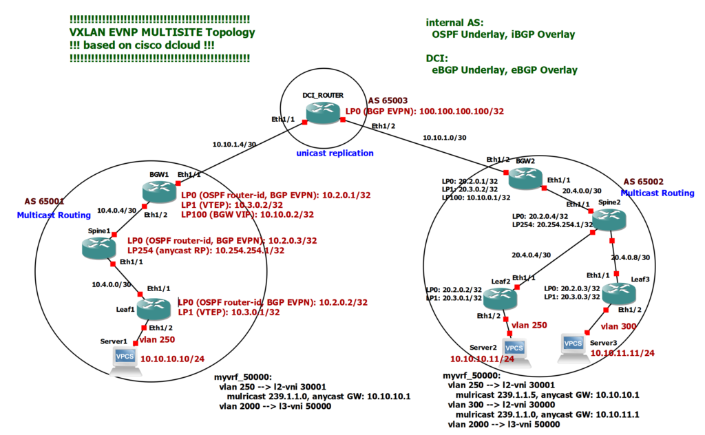
In Site1 we have two leaf switches and one spine switch. One of the leaf switches acts as a border leaf switch with border gateway capability. In Site2 we have three leaf switches. One of the leaf switches acts as a border leaf switch with border gateway capability.
Loopback0 of switches with IP Subnet 10.2.0.x In site1 and 20.2.0.x in site2 are used as OSPF router-id and MP-BGP EVPN neighborship.
Loopback1 of leaf switches with IP subnet 10.3.0.x in Site1 and 20.3.0.x in Site2 are used as VTEP addresses for VXLAN tunnel termination.
Loopback254 in spine switches with IP subnet 10.254.254.x in Site1 and 20.254.254.x in Site2 serve as the anycast RP address for implementing multicast routing.
Loopback 100 in border gateways with IP subnet 10.10.0.x serves as the virtual IP address of the border gateway, which is shared by the border gateways at each site. Although there is only one border gateway at each site in this topology, but having border gateway virtual IP is required to implement multisite VXLAN EVPN solution.
In the first site, server1 is connected to leaf1 switch in VLAN 250 and with IP address 10.10.10.10. VLAN 250 is mapped to L2 VNI 30001 with anycast gateway 10.10.10.1. VLAN 2000 mapped to L3 VNI 50000 for the purpose of inter-VXLAN routing is also configured in site1.
In Site2 we have two VLANs, VLAN 250 and VLAN 300, which are mapped to L2 VNI 30001 and 30000. VLAN 2000 and L3 VNI 50000 which is used for inter-VXLAN routing, must also be configured in Site2.
Server2 with IP Address 10.10.10.11 is connected to Leaf2 switch in Site2 with VLAN 250. Server2 is located here to check L2 connectivity with Server1 in Site1. Server3 with IP Address 10.10.11.11 is connected to Leaf3 Switch in Site2 and in VLAN 300. Server3 is located here to check L3 connectivity with Server1 in Site1. So we can check both L2 and L3 connectivity between two sites if we wish.
VXLAN multisite Configuration
To start configuration, we need to implement VXLAN EVPN in each site independently as we implemented in the first and second VXLAN configuration examples. note, however, that in this step we consider border gateways as normal leaf switches. In the next few steps we will discuss the configuration that is specific to Border Gateways.
9. VXLAN EVPN Configuration Example1 Part1
10. VXLAN EVPN Configuration Example1 Part2
11. VXLAN BGP EVPN Configuration Example2
We implement multicast routing for forwarding BUM traffic with PIM sparse mode and spine switch as anycast RP at both sites as we have done in our first Configuration Example. But between sites we implement unicast replication for forwarding BUM traffic since we normally, cannot implement multicast routing between sites because DCI infrastructure is not under our management.
What we have added in the VXLAN multisite configuration is the external BGP configuration between two sites and also the configuration of border gateway, which we want to discuss more about in this video.
!!! leaf1
route-map rmap-redist-direct permit 10
  match tag 54321
!
router bgp 65001
  router-id 10.2.0.1
  address-family ipv4 unicast
    redistribute direct route-map rmap-redist-direct
    maximum-paths 64
    maximum-paths ibgp 64
  neighbor 10.10.1.5
    remote-as 65003
    update-source Ethernet1/1
    address-family ipv4 unicast
      next-hop-self
!!! DCI
router bgp 65003
address-family ipv4 unicast
network 100.100.100.100/32
maximum-paths 64
maximum-paths ibgp 64
neighbor 10.10.1.2
remote-as 65002
update-source Ethernet1/2
address-family ipv4 unicast
next-hop-self
neighbor 10.10.1.6
remote-as 65001
update-source Ethernet1/1
address-family ipv4 unicast
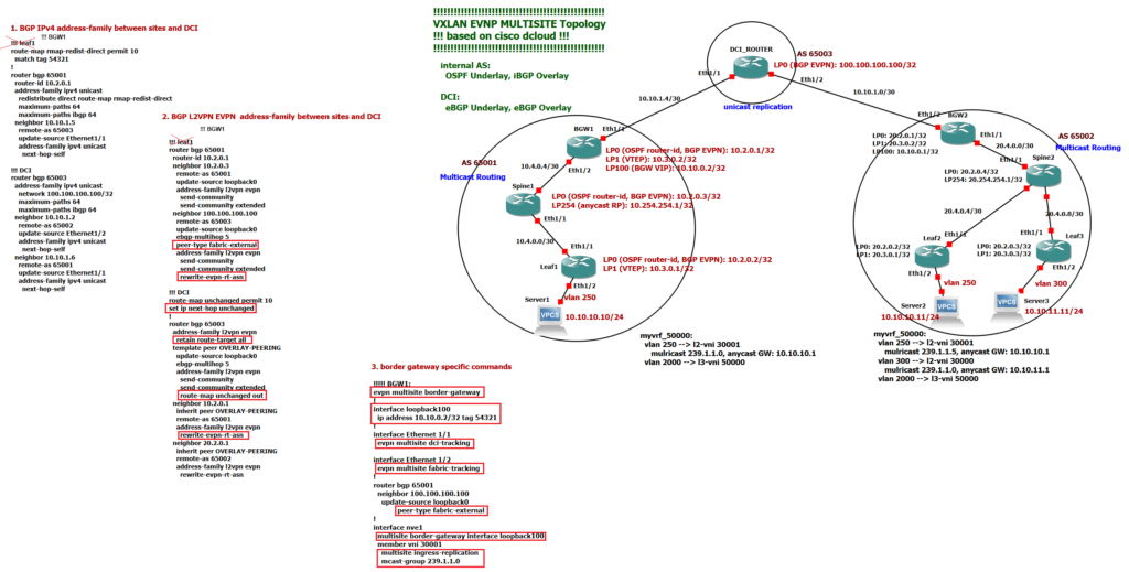
next-hop-selfWe have two external BGP configurations between sites and DCI route server. first, external BGP configuration with IPV4 address family. The purpose of the BGP IPv4 address family is to advertise the loopback address of border gateways and also the loopback of DCI so they are made known to each other and border gateways at two sites can communicate with each other and also with the DCI loopback interface. Through this communication we will configure our next BGP, which is an external BGP with L2VPN EVPN address family between sites and DCI loopback interfaces which advertises MAC and IP addresses between sites. As you know, BGP EVPN is used to make MAC and IP addresses of two sites to each other known.
!!! leaf1
router bgp 65001
  router-id 10.2.0.1
  neighbor 10.2.0.3
    remote-as 65001
    update-source loopback0
    address-family l2vpn evpn
      send-community
      send-community extended
  neighbor 100.100.100.100
    remote-as 65003
    update-source loopback0
    ebgp-multihop 5
    peer-type fabric-external
    address-family l2vpn evpn
      send-community
      send-community extended
      rewrite-evpn-rt-asn
!!! DCI
router bgp 65003
address-family l2vpn evpn
retain route-target all
template peer OVERLAY-PEERING
update-source loopback0
ebgp-multihop 5
address-family l2vpn evpn
send-community
send-community extended
route-map unchanged out
neighbor 10.2.0.1
inherit peer OVERLAY-PEERING
remote-as 65001
address-family l2vpn evpn
rewrite-evpn-rt-asn
neighbor 20.2.0.1
inherit peer OVERLAY-PEERING
remote-as 65002
address-family l2vpn evpn
rewrite-evpn-rt-asn
As we have explained in the second configuration Example, when we configure external BGP for L2VPN EVPN then we have to configure “next-hop unchanged” in route-server, so border gateways see each other directly as next-hop address and route-server is not next-hop address. This is required to create VXLAN tunnel between border gateways.
In addition, we have to configure “retain route-target all” in the route server so that received routes are not filtered because of RT values which are not matched between sites and route server. this is because AS numbers are different in sites and also DCI and AS number is part of the RT Values.
Another command that is required when configuring external BGP for the L2VPN EVPN address family is “rewrite-evpn-rt-asn”. this command must be configured both in the route server and in the border gateways. This command changes the AS number of RT value of the receiving routes to the AS number of the receiving router so that the route can be imported into VRF and VNI.
Border Gateway Configuration
now let’s discuss the commands which are specific for border gateways configuration.
!!!!! BGW1:
evpn multisite border-gateway
!
interface loopback100
  ip address 10.10.0.2/32 tag 54321
!
interface Ethernet 1/1
  evpn multisite dci-tracking

interface Ethernet 1/2
  evpn multisite fabric-tracking
!
router bgp 65001
  neighbor 100.100.100.100
    update-source loopback0
            peer-type fabric-external
!
interface nve1
  multisite border-gateway interface loopback100
  member vni 30001
    multisite ingress-replication
    mcast-group 239.1.1.0
The “evpn multisite border-gateway” command is used to activate the border gateway function in border-leaf switch. This command enables hierarchical VXLAN tunnels.
The Loopback 100 interface is configured with one IP address which is the same in two border gateways at each site, if we have multiple border gateways at each site. This IP address is used as a VIP in both border gateways. So if one border gateway is interrupted, our VXLAN tunnel will not be interrupted. Here we only have one border gateway, but VIP needs to be configured.
The commands “evpn multisite dci-tracking” and “evpn multisite fabric-tracking” are used to track interfaces connected to DCI and spine switches. If one of these interfaces fails, the VIP of the border gateway connected to these interfaces is automatically shut down so that the VXLAN tunnel is rerouted to another border gateway.
The command “peer-type fabric-external” in border gateway for the neighbor DCI in L2VPN EVPN address-family is required which enable next-hop rewrite for multisite VXLAN. In other words IP address of loopback 100 interface which is used as VIP address will be used as next-hop address in VXLAN Tunnel in multisite configuration.
Last two commands in “interface nve” in border gateway are not new. But I wanted to emphasis that both multicast routing method und unicast replication method are enabled in border gateways to handle BUM traffic. Multicast routing is enabled inside each site but unicast replication method is used between sites since it is not under our management and we can not enable multicast routing between sites.
The final point is that if you want to filter the traffic of a particular VLAN between sites, it is sufficient that you do not configure that VLAN in the border gateway. In our topology we have not configured VLAN 300 in Border Gateway 2, so communication with VLAN 300 from Site1 is not possible.
VXLAN multisite configuration verfification
Now let’s check the communication between server1 and server2 in VLAN 250.
Also check BGP table for L2VPN EVPN Address Family in leaf switch and border gateway.
Leaf1# show bgp l2vpn evpn
BGP routing table information for VRF default, address family L2VPN EVPN
BGP table version is 2064, Local Router ID is 10.2.0.2
Status: s-suppressed, x-deleted, S-stale, d-dampened, h-history, *-valid, >-best
Path type: i-internal, e-external, c-confed, l-local, a-aggregate, r-redist, I-i
njected
Origin codes: i - IGP, e - EGP, ? - incomplete, | - multipath, & - backup, 2 - b
est2

   Network            Next Hop            Metric     LocPrf     Weight Path
Route Distinguisher: 10.2.0.1:33017
*>i[2]:[0]:[0]:[48]:[000c.2945.0180]:[0]:[0.0.0.0]/216
                      10.3.0.2                          100          0 i

Route Distinguisher: 10.2.0.2:33017    (L2VNI 30001)
*>i[2]:[0]:[0]:[48]:[000c.293b.3426]:[0]:[0.0.0.0]/216
                      10.10.0.2                         100          0 65003 650
02 i
*>i[2]:[0]:[0]:[48]:[000c.2945.0180]:[0]:[0.0.0.0]/216
                      10.3.0.2                          100          0 i
*>i[2]:[0]:[0]:[48]:[000c.29a9.8a1a]:[0]:[0.0.0.0]/216
                      10.10.0.2                         100          0 65003 650
02 i
*>l[2]:[0]:[0]:[48]:[0050.56b1.4f84]:[0]:[0.0.0.0]/216
                      10.3.0.1                          100      32768 i
*>i[2]:[0]:[0]:[48]:[000c.29a9.8a1a]:[32]:[10.10.10.11]/272
                      10.10.0.2                         100          0 65003 650
02 i
*>l[2]:[0]:[0]:[48]:[0050.56b1.4f84]:[32]:[10.10.10.10]/272
                      10.3.0.1                          100      32768 i

Route Distinguisher: 20.2.0.1:33017
*>i[2]:[0]:[0]:[48]:[000c.293b.3426]:[0]:[0.0.0.0]/216
                      10.10.0.2                         100          0 65003 650
02 i

Route Distinguisher: 20.2.0.2:33017
*>i[2]:[0]:[0]:[48]:[000c.29a9.8a1a]:[0]:[0.0.0.0]/216
                      10.10.0.2                         100          0 65003 650
02 i
*>i[2]:[0]:[0]:[48]:[000c.29a9.8a1a]:[32]:[10.10.10.11]/272
                      10.10.0.2                         100          0 65003 650
02 i
Leaf1# show l2route mac-ip all
Flags -(Rmac):Router MAC (Stt):Static (L):Local (R):Remote (V):vPC link
(Dup):Duplicate (Spl):Split (Rcv):Recv(D):Del Pending (S):Stale (C):Clear
(Ps):Peer Sync (Ro):Re-Originated (Orp):Orphan
Topology    Mac Address    Host IP         Prod   Flags         Seq No     Next-
Hops
----------- -------------- --------------- ------ ---------- ---------------
250         0050.56b1.4f84 10.10.10.10     HMM    --            0         Local

250         000c.29a9.8a1a 10.10.10.11     BGP    --            0         10.10.0.2
Leaf1#
BGW1(config)# show l2route mac-ip all
Flags -(Rmac):Router MAC (Stt):Static (L):Local (R):Remote (V):vPC link
(Dup):Duplicate (Spl):Split (Rcv):Recv(D):Del Pending (S):Stale (C):Clear
(Ps):Peer Sync (Ro):Re-Originated (Orp):Orphan
Topology Mac Address Host IP Prod Flags Seq No Next-
Hops
----------- -------------- --------------- ------ ---------- ---------------
250 0050.56b1.4f84 10.10.10.10 BGP -- 0 10.3.0.1
250 000c.29a9.8a1a 10.10.10.11 BGP -- 0 10.10.0.1 BGW1(config)# show bgp l2vpn evpn
BGP routing table information for VRF default, address family L2VPN EVPN
BGP table version is 2771, Local Router ID is 10.2.0.1
Status: s-suppressed, x-deleted, S-stale, d-dampened, h-history, *-valid, >-best
Path type: i-internal, e-external, c-confed, l-local, a-aggregate, r-redist, I-i
njected
Origin codes: i - IGP, e - EGP, ? - incomplete, | - multipath, & - backup, 2 - b
est2
Network Next Hop Metric LocPrf Weight Path
Route Distinguisher: 10.2.0.1:27001 (ES [0300.0000.00fd.e900.0309 0])
*>l[4]:[0300.0000.00fd.e900.0309]:[32]:[10.3.0.2]/136
10.3.0.2 100 32768 i
Route Distinguisher: 10.2.0.1:33017 (L2VNI 30001)
*>e[2]:[0]:[0]:[48]:[000c.293b.3426]:[0]:[0.0.0.0]/216
20.3.0.2 0 65003 650
02 i
*>l[2]:[0]:[0]:[48]:[000c.2945.0180]:[0]:[0.0.0.0]/216
10.3.0.2 100 32768 i
*>e[2]:[0]:[0]:[48]:[000c.29a9.8a1a]:[0]:[0.0.0.0]/216
10.10.0.1 0 65003 650
02 i
*>i[2]:[0]:[0]:[48]:[0050.56b1.4f84]:[0]:[0.0.0.0]/216
10.3.0.1 100 0 i
*>e[2]:[0]:[0]:[48]:[000c.29a9.8a1a]:[32]:[10.10.10.11]/272
10.10.0.1 0 65003 650
02 i
*>i[2]:[0]:[0]:[48]:[0050.56b1.4f84]:[32]:[10.10.10.10]/272
10.3.0.1 100 0 i
*>l[3]:[0]:[32]:[10.3.0.2]/88
10.3.0.2 100 32768 i
*>e[3]:[0]:[32]:[20.3.0.2]/88
20.3.0.2 0 65003 650
02 i
Route Distinguisher: 10.2.0.2:33017
*>i[2]:[0]:[0]:[48]:[0050.56b1.4f84]:[0]:[0.0.0.0]/216
10.3.0.1 100 0 i
*>i[2]:[0]:[0]:[48]:[0050.56b1.4f84]:[32]:[10.10.10.10]/272
10.3.0.1 100 0 i
Route Distinguisher: 20.2.0.1:33017
*>e[2]:[0]:[0]:[48]:[000c.293b.3426]:[0]:[0.0.0.0]/216
20.3.0.2 0 65003 650
02 i
*>e[3]:[0]:[32]:[20.3.0.2]/88
20.3.0.2 0 65003 650
02 i
Route Distinguisher: 20.2.0.2:33017
*>e[2]:[0]:[0]:[48]:[000c.29a9.8a1a]:[0]:[0.0.0.0]/216
10.10.0.1 0 65003 650
02 i
*>e[2]:[0]:[0]:[48]:[000c.29a9.8a1a]:[32]:[10.10.10.11]/272
10.10.0.1 0 65003 650
02 i
As you can see, Next-Hop in Leaf1-Switch for the IP address in Site2, 10.10.10.11, points to Border-Gateway1. in Border-Gateway1, it points to Border-Gateway2 and in Border-Gateway2, it points to Leaf2-Switch that show how hierarchical VXLAN tunnel is created in multisite solution.
download full configuration of VXLAN multisite configuration
Thanks for Sharing 🙂
Very Useful for learning VXLAN.
Thanks. you are welcome