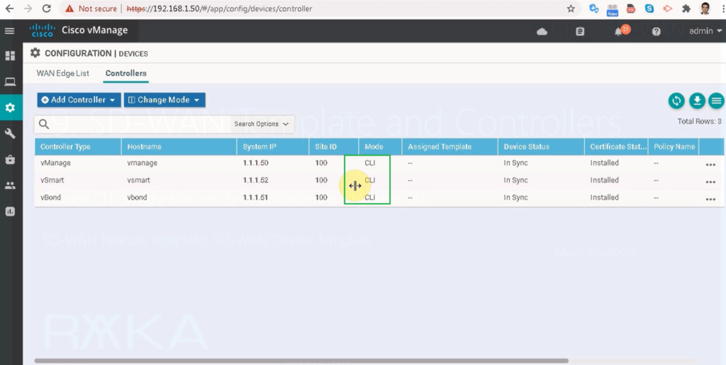
in the next step we change vSmart configuration mode from CLI to GUI
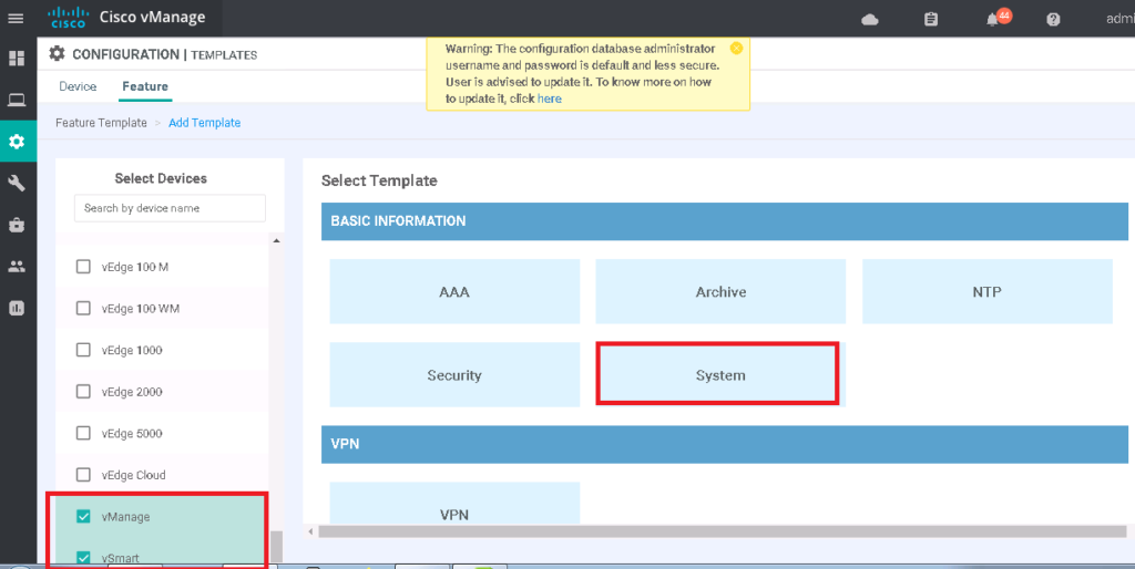
First we add a feature template for system configuration
device type: vSmart
Template: System
Template Name: vSmart_SYSTEM
Description: vSmart _SYSTEM
Section: Basic Configuration
| Parameter | scope | Value |
|---|---|---|
| Site ID | Device Specific | |
| System IP | Device Specific | |
| Timezone | Global | Asia/Tehran |
| Hostname | Device Specific |
then we add vSmart feature template for NTP configuration
device type: vSmart
Template: NTP
Template Name: vSmart_NTP
Description: vSmart_NTP
Section: Server
| Parameter | scope | Value |
|---|---|---|
| Hostname/IP Address | Global | 37.156.28.13 |
| Prefer | Global | On |
then we add a feature template for username/password to edit admin password and add a new user
device type: vSmart
Template: AAA
Template Name: vSmart_AAA
Description: vSmart_AAA
Section: Local
| Parameter | scope | Value |
|---|---|---|
| Name | Global | admin/majid |
| Password | Global | rayka-co.com |
| User Groups | Global | netadmin |
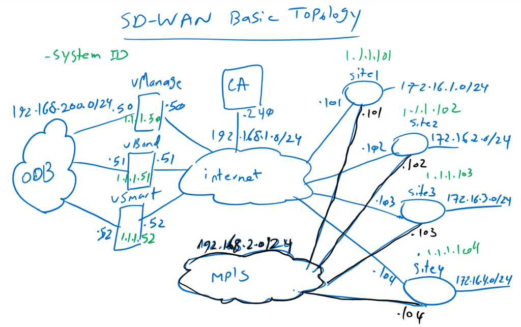
As you know, We need two VPNs in vSmart. VPN0 as default VRF for connecting transport internet and MPLS links and VPN 512 as Management VRF.
device type: vSmart
Template: VPN
Template Name: vSmart_VPN0
Description: vSmart_VPN0
Section: Basic Configuration
| Parameter | Parameter | Value |
|---|---|---|
| VPN | Global | 0 |
| name | Global | VPN0 |
Section: IPV4 Route
We need also a default route in VPN0.
| Parameter | scope | Value |
|---|---|---|
| Prefix | Global | 0.0.0.0/0 |
| Next Hop | Global | Add Next Hop -> 192.168.1.1 |
Now we create VPN 512.
device type: vSmart
Template: VPN
Template Name: vSmart_VPN512
Description: vSmart_VPN512
Section: Basic Configuration
| Parameter | scope | Value |
|---|---|---|
| VPN | Global | 512 |
| name | Global | VPN512 |
Now we have to add one interface in VPN0 and one interface in VPN512.
device type: vSmart
Template: VPN Interface Ethernet
Template Name: vSmart_Interface_Internet
Description: vSmart_Interface_Internet
Section: Basic Configuration
| Parameter | scope | Value |
|---|---|---|
| shutdown | Global | No |
| Interface Name | Global | eth1 |
| Description | Global | *** Internet *** |
| IP Address/ Prefix Length | Global | 192.168.1.52/24 |
Section: Tunnel
| Parameter | scope | Value |
|---|---|---|
| Tunnel Interface | Global | On |
| Color | Global | Public-internet |
| Allow Service All | Global | On |
device type: vSmart
Template: VPN Interface Ethernet
Template Name: vSmart_Interface_OOB
Description: vSmart_Interface_OOB
Section: Basic Configuration
| Parameter | scope | Value |
|---|---|---|
| shutdown | Global | No |
| Interface Name | Global | eth0 |
| Description | Global | *** OOB *** |
| IP Address/ Prefix Length | Global | 192.168.200.52/24 |
Now we will create device template from feature template.
configurations -> templates -> device -> create template à from feature templateDevice Model: vSmart
Template Name: vSmart_Device_Template
Description: vSmart_Device_Template
Section: Basic Configuration
| Parameter | Value |
|---|---|
| System | vSmart_SYSTEM |
| NTP | vSmart_NTP |
| AAA | vSmart_AAA |
Section: Transport & Management VPN
| Parameter | Value |
|---|---|
| VPN 0 | vSmart_VPN0 |
| VPN Interface Ethernet | vSmart_Interface_Internet |
| VPN 512 | vSmart_VPN512 |
| VPN Interface Ethernet | vSmart_Interface_OOB |
Now let’s attach vSmart to apply this configuration. in this step, device specific values must be given as follows.
| Parameter | Value |
|---|---|
| Hosname | vSamrt |
| Site-ID | 100 |
| System-ID | 1.1.1.52 |
we can review the configuration and apply it when it is ok.
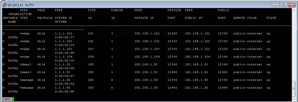
After applying the configuration, we have to make sure that controllers and WAN edge routers are still up.
SD-WAN Template: vBond change from CLI to vManage
in the next step we change vBond configuration mode from CLI to GUI
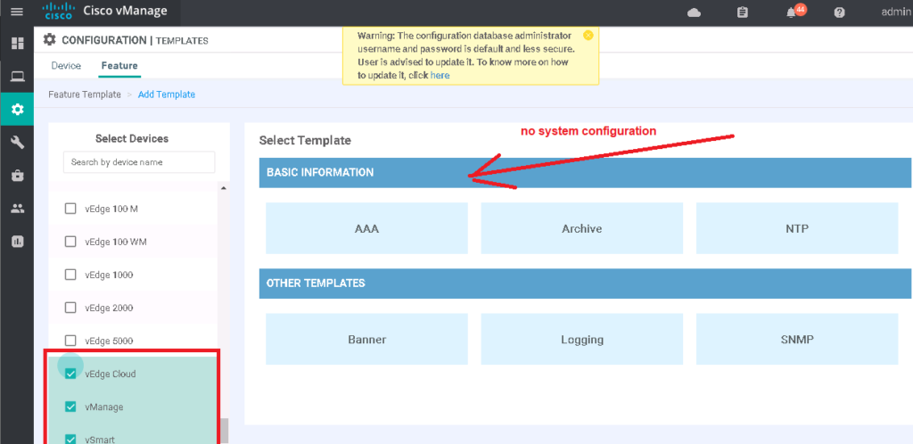
vBond has the same image as vEdge cloud. So we choose vEdge cloud as vBond controller.
device type: vEdge Cloud
Template: System
Template Name: vBond_SYSTEM
Description: vBond_SYSTEM
Section: Basic Configuration
| Parameter | scope | Value |
|---|---|---|
| Site ID | Device Specific | |
| System IP | Device Specific | |
| Timezone | Global | Asia/Tehran |
| Hostname | Device Specific | |
| Console Baud Rate | Global | 115200 |
then we add vBond feature template for NTP configuration
device type: vEdge Cloud
Template: NTP
Template Name: vBond_NTP
Description: vBond_NTP
Section: Server
| Parameter | scope | Value |
|---|---|---|
| Hostname/IP Address | Global | 37.156.28.13 |
| Prefer | Global | On |
then we add a feature template for username/password to edit admin password and add a new user
device type: vEdge Cloud
Template: AAA
Template Name: vBond_AAA
Description: vBond_AAA
Section: Local
| Parameter | scope | Value |
|---|---|---|
| Name | Global | admin/majid |
| Password | Global | rayka-co.com |
| User Groups | Global | netadmin |
As you know, We need two VPNs in vBond. VPN0 as default VRF for connecting transport internet and MPLS links and VPN 512 as Management VRF.
device type: vEdge Cloud
Template: VPN
Template Name: vBond_VPN0
Description: vBond_VPN0
Section: Basic Configuration
| Parameter | scope | Value |
|---|---|---|
| VPN | Global | 0 |
| name | Global | VPN0 |
Section: IPV4 Route
We need also a default route in VPN0.
| Parameter | scope | Value |
|---|---|---|
| Prefix | Global | 0.0.0.0/0 |
| Next Hop | Global | Add Next Hop -> 192.168.1.1 |
Now we create VPN 512.
device type: vEdge Cloud
Template: VPN
Template Name: vBond_VPN512
Description: vBond_VPN512
Section: Basic Configuration
| Parameter | scope | Value |
|---|---|---|
| VPN | Global | 512 |
| name | Global | VPN512 |
Now we have to add one interface in VPN0 and one interface in VPN512.
device type: vEdge Cloud
Template: VPN Interface Ethernet
Template Name: vBond_Interface_Internet
Description: vBond_Interface_Internet
Section: Basic Configuration
| Parameter | scope | Value |
|---|---|---|
| shutdown | Global | No |
| Interface Name | Global | eth1 |
| Description | Global | *** Internet *** |
| IP Address/ Prefix Length | Global | 192.168.1.51/24 |
Section: Tunnel
| Parameter | scope | Value |
|---|---|---|
| Tunnel Interface | Global | On |
| Color | Global | Public-internet |
| Allow Service All | Global | On |
device type: vEdge Cloud
Template: VPN Interface Ethernet
Template Name: vBond_Interface_OOB
Description: vBond_Interface_OOB
Section: Basic Configuration
| Parameter | scope | Value |
|---|---|---|
| shutdown | Global | No |
| Interface Name | Global | eth0 |
| Description | Global | *** OOB *** |
| IP Address/ Prefix Length | Global | 192.168.200.51/24 |
Now we will create device template from feature template.
configurations -> templates -> device -> create template à from feature templateDevice Model: vEdge Cloud
Template Name: vBond_Device_Template
Description: vBond_Device_Template
Section: Basic Configuration
| Parameter | Value |
|---|---|
| System | vBond_SYSTEM |
| NTP | vBond_NTP |
| AAA | vBond_AAA |
Section: Transport & Management VPN
| Parameter | Value |
|---|---|
| VPN 0 | vBand_VPN0 |
| VPN Interface | vBond_Interface_Internet |
| VPN 512 | vBond_VPN512 |
| VPN Interface | vBond_Interface_OOB |
Now let’s attach vBond to apply this configuration.
Now let’s attach vBond to apply this configuration. in this step, device specific values must be given as follows.
| Parameter | Value |
|---|---|
| Hosname | vBond |
| Site-ID | 100 |
| System-ID | 1.1.1.51 |
we can review the configuration and apply it when it is ok.
After applying the configuration, we have to make sure that controllers and WAN edge routers are still up.
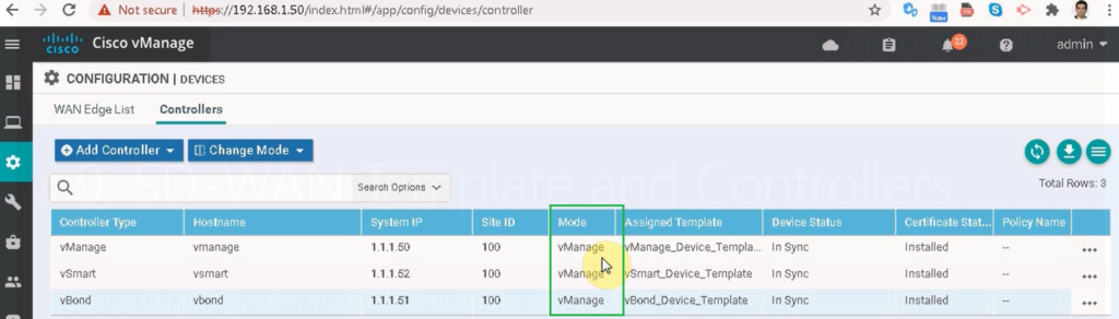
And also good to check if configuration mode of vBond has changed from CLI to vManage.
so I prefer to use different feature templates for each controller here.
4. cisco SD-WAN vManage Installation and Configurationn (20.3.4)
5. Cisco SD-WAN vBond Installation (Version 20.3.4)
6. cisco SD-WAN vSmart Installation (Version 20.3.4)
SD-WAN Template in cisco website
SD-WAN Template: vManage from CLI to GUI
we start with vManage controller to change configuration mode from CLI to GUI
First we add a feature template for system configuration
device type: vManage
Template: System
Template Name: vManage_SYSTEM
Description: vManage_SYSTEM
Section: Basic Configuration
| Parameter | scope | Value |
|---|---|---|
| Site ID | Device Specific | |
| System IP | Device Specific | |
| Timezone | Global | Asia/Tehran |
| Hostname | Device Specific |
then we add vManage feature template for NTP configuration
device type: vManage
Template: NTP
Template Name: vManage_NTP
Description: vManage_NTP
Section: Server
| Parameter | scope | Value |
|---|---|---|
| Hostname/IP Address | Global | 37.156.28.13 |
| Prefer | Global | On |
then we add a feature template for username/password to edit admin password and add a new user
device type: vManage
Template: AAA
Template Name: vManage_AAA
Description: vManage_AAA
Section: Local
| Parameter | scope | Value |
|---|---|---|
| Name | Global | admin/majid |
| Password | Global | rayka-co.com |
| User Groups | Global | netadmin |
As you know, We need two VPNs in vManage. VPN0 as default VRF for connecting transport internet and MPLS links and VPN 512 as Management VRF.
device type: vManage
Template: VPN
Template Name: vManage_VPN0
Description: vManage_VPN0
Section: Basic Configuration
| Parameter | scope | Value |
|---|---|---|
| VPN | Global | 0 |
| name | Global | VPN0 |
Section: IPV4 Route
We need also a default route in VPN0.
| Parameter | scope | Value |
|---|---|---|
| Prefix | Global | 0.0.0.0/0 |
| Next Hop | Global | Add Next Hop -> 192.168.1.1 |
Now we create VPN 512 feature Template.
device type: vManage
Template: VPN
Template Name: vManage_VPN512
Description: vManage_VPN512
Section: Basic Configuration
| Parameter | scope | Value |
|---|---|---|
| VPN | Global | 512 |
| name | Global | VPN512 |
Now we have to add one interface in VPN0 and one interface in VPN512.
device type: vManage
Template: VPN Interface Ethernet
Template Name: vManage_Interface_Internet
Description: vmanage_Interface_Internet
Section: Basic Configuration
| Parameter | scope | Value |
|---|---|---|
| shutdown | Global | No |
| Interface Name | Global | eth1 |
| Description | Global | *** Internet *** |
| IP Address/ Prefix Length | Global | 192.168.1.50/24 |
Section: Tunnel
| Parameter | scope | Value |
|---|---|---|
| Tunnel Interface | Global | On |
| Color | Global | Public-internet |
| Allow Service All | Global | On |
device type: vManage
Template: VPN Interface Ethernet
Template Name: vManage_Interface_OOB
Description: vmanage_Interface_OOB
Section: Basic Configuration
| Parameter | scope | Value |
|---|---|---|
| shutdown | Global | No |
| Interface Name | Global | eth0 |
| Description | Global | *** OOB *** |
| IP Address/ Prefix Length | Global | 192.168.200.50/24 |
Now we will create device template from feature template.
configurations -> templates -> device -> create template à from feature templateDevice Model: vManage
Template Name: vmanage_Device_Template
Description: vManage_Device_Template
Section: Basic Configuration
| Parameter | Value |
|---|---|
| System | vManage_SYSTEM |
| NTP | vManage _NTP |
| AAA | vManage _AAA |
Section: Transport & Management VPN
| Parameter | Value |
| VPN 0 | vManage_VPN0 |
| VPN Interface Ethernet | vManage_Interface_Internet |
| VPN 512 | vManage_VPN512 |
| VPN Interface Ethernet | vManage_Interface_OOB |
Now let’s attach vManage to apply this configuration. in this step, device specific values must be given as follows.
| Parameter | Value |
|---|---|
| Hosname | vManage |
| Site-ID | 100 |
| System-ID | 1.1.1.50 |
we can review the configuration and apply it when it is ok.
After applying the configuration, we have to make sure that controllers and WAN edge routers are still up.
And also good to check if configuration mode of vManage has changed from CLI to vManage.
SD-WAN Template: vSmart from CLI to vManage GUI
in the next step we change vSmart configuration mode from CLI to GUI
First we add a feature template for system configuration
device type: vSmart
Template: System
Template Name: vSmart_SYSTEM
Description: vSmart _SYSTEM
Section: Basic Configuration
| Parameter | scope | Value |
|---|---|---|
| Site ID | Device Specific | |
| System IP | Device Specific | |
| Timezone | Global | Asia/Tehran |
| Hostname | Device Specific |
then we add vSmart feature template for NTP configuration
device type: vSmart
Template: NTP
Template Name: vSmart_NTP
Description: vSmart_NTP
Section: Server
| Parameter | scope | Value |
|---|---|---|
| Hostname/IP Address | Global | 37.156.28.13 |
| Prefer | Global | On |
then we add a feature template for username/password to edit admin password and add a new user
device type: vSmart
Template: AAA
Template Name: vSmart_AAA
Description: vSmart_AAA
Section: Local
| Parameter | scope | Value |
|---|---|---|
| Name | Global | admin/majid |
| Password | Global | rayka-co.com |
| User Groups | Global | netadmin |
As you know, We need two VPNs in vSmart. VPN0 as default VRF for connecting transport internet and MPLS links and VPN 512 as Management VRF.
device type: vSmart
Template: VPN
Template Name: vSmart_VPN0
Description: vSmart_VPN0
Section: Basic Configuration
| Parameter | Parameter | Value |
|---|---|---|
| VPN | Global | 0 |
| name | Global | VPN0 |
Section: IPV4 Route
We need also a default route in VPN0.
| Parameter | scope | Value |
|---|---|---|
| Prefix | Global | 0.0.0.0/0 |
| Next Hop | Global | Add Next Hop -> 192.168.1.1 |
Now we create VPN 512.
device type: vSmart
Template: VPN
Template Name: vSmart_VPN512
Description: vSmart_VPN512
Section: Basic Configuration
| Parameter | scope | Value |
|---|---|---|
| VPN | Global | 512 |
| name | Global | VPN512 |
Now we have to add one interface in VPN0 and one interface in VPN512.
device type: vSmart
Template: VPN Interface Ethernet
Template Name: vSmart_Interface_Internet
Description: vSmart_Interface_Internet
Section: Basic Configuration
| Parameter | scope | Value |
|---|---|---|
| shutdown | Global | No |
| Interface Name | Global | eth1 |
| Description | Global | *** Internet *** |
| IP Address/ Prefix Length | Global | 192.168.1.52/24 |
Section: Tunnel
| Parameter | scope | Value |
|---|---|---|
| Tunnel Interface | Global | On |
| Color | Global | Public-internet |
| Allow Service All | Global | On |
device type: vSmart
Template: VPN Interface Ethernet
Template Name: vSmart_Interface_OOB
Description: vSmart_Interface_OOB
Section: Basic Configuration
| Parameter | scope | Value |
|---|---|---|
| shutdown | Global | No |
| Interface Name | Global | eth0 |
| Description | Global | *** OOB *** |
| IP Address/ Prefix Length | Global | 192.168.200.52/24 |
Now we will create device template from feature template.
configurations -> templates -> device -> create template à from feature templateDevice Model: vSmart
Template Name: vSmart_Device_Template
Description: vSmart_Device_Template
Section: Basic Configuration
| Parameter | Value |
|---|---|
| System | vSmart_SYSTEM |
| NTP | vSmart_NTP |
| AAA | vSmart_AAA |
Section: Transport & Management VPN
| Parameter | Value |
|---|---|
| VPN 0 | vSmart_VPN0 |
| VPN Interface Ethernet | vSmart_Interface_Internet |
| VPN 512 | vSmart_VPN512 |
| VPN Interface Ethernet | vSmart_Interface_OOB |
Now let’s attach vSmart to apply this configuration. in this step, device specific values must be given as follows.
| Parameter | Value |
|---|---|
| Hosname | vSamrt |
| Site-ID | 100 |
| System-ID | 1.1.1.52 |
we can review the configuration and apply it when it is ok.
After applying the configuration, we have to make sure that controllers and WAN edge routers are still up.
SD-WAN Template: vBond change from CLI to vManage
in the next step we change vBond configuration mode from CLI to GUI
vBond has the same image as vEdge cloud. So we choose vEdge cloud as vBond controller.
device type: vEdge Cloud
Template: System
Template Name: vBond_SYSTEM
Description: vBond_SYSTEM
Section: Basic Configuration
| Parameter | scope | Value |
|---|---|---|
| Site ID | Device Specific | |
| System IP | Device Specific | |
| Timezone | Global | Asia/Tehran |
| Hostname | Device Specific | |
| Console Baud Rate | Global | 115200 |
then we add vBond feature template for NTP configuration
device type: vEdge Cloud
Template: NTP
Template Name: vBond_NTP
Description: vBond_NTP
Section: Server
| Parameter | scope | Value |
|---|---|---|
| Hostname/IP Address | Global | 37.156.28.13 |
| Prefer | Global | On |
then we add a feature template for username/password to edit admin password and add a new user
device type: vEdge Cloud
Template: AAA
Template Name: vBond_AAA
Description: vBond_AAA
Section: Local
| Parameter | scope | Value |
|---|---|---|
| Name | Global | admin/majid |
| Password | Global | rayka-co.com |
| User Groups | Global | netadmin |
As you know, We need two VPNs in vBond. VPN0 as default VRF for connecting transport internet and MPLS links and VPN 512 as Management VRF.
device type: vEdge Cloud
Template: VPN
Template Name: vBond_VPN0
Description: vBond_VPN0
Section: Basic Configuration
| Parameter | scope | Value |
|---|---|---|
| VPN | Global | 0 |
| name | Global | VPN0 |
Section: IPV4 Route
We need also a default route in VPN0.
| Parameter | scope | Value |
|---|---|---|
| Prefix | Global | 0.0.0.0/0 |
| Next Hop | Global | Add Next Hop -> 192.168.1.1 |
Now we create VPN 512.
device type: vEdge Cloud
Template: VPN
Template Name: vBond_VPN512
Description: vBond_VPN512
Section: Basic Configuration
| Parameter | scope | Value |
|---|---|---|
| VPN | Global | 512 |
| name | Global | VPN512 |
Now we have to add one interface in VPN0 and one interface in VPN512.
device type: vEdge Cloud
Template: VPN Interface Ethernet
Template Name: vBond_Interface_Internet
Description: vBond_Interface_Internet
Section: Basic Configuration
| Parameter | scope | Value |
|---|---|---|
| shutdown | Global | No |
| Interface Name | Global | eth1 |
| Description | Global | *** Internet *** |
| IP Address/ Prefix Length | Global | 192.168.1.51/24 |
Section: Tunnel
| Parameter | scope | Value |
|---|---|---|
| Tunnel Interface | Global | On |
| Color | Global | Public-internet |
| Allow Service All | Global | On |
device type: vEdge Cloud
Template: VPN Interface Ethernet
Template Name: vBond_Interface_OOB
Description: vBond_Interface_OOB
Section: Basic Configuration
| Parameter | scope | Value |
|---|---|---|
| shutdown | Global | No |
| Interface Name | Global | eth0 |
| Description | Global | *** OOB *** |
| IP Address/ Prefix Length | Global | 192.168.200.51/24 |
Now we will create device template from feature template.
configurations -> templates -> device -> create template à from feature templateDevice Model: vEdge Cloud
Template Name: vBond_Device_Template
Description: vBond_Device_Template
Section: Basic Configuration
| Parameter | Value |
|---|---|
| System | vBond_SYSTEM |
| NTP | vBond_NTP |
| AAA | vBond_AAA |
Section: Transport & Management VPN
| Parameter | Value |
|---|---|
| VPN 0 | vBand_VPN0 |
| VPN Interface | vBond_Interface_Internet |
| VPN 512 | vBond_VPN512 |
| VPN Interface | vBond_Interface_OOB |
Now let’s attach vBond to apply this configuration.
Now let’s attach vBond to apply this configuration. in this step, device specific values must be given as follows.
| Parameter | Value |
|---|---|
| Hosname | vBond |
| Site-ID | 100 |
| System-ID | 1.1.1.51 |
we can review the configuration and apply it when it is ok.
After applying the configuration, we have to make sure that controllers and WAN edge routers are still up.
And also good to check if configuration mode of vBond has changed from CLI to vManage.